
Composite material reinforced part and forming process method

A composite material and molding process technology, which is used in the field of solid rocket motors to ensure structural integrity, improve overall stiffness, and improve overall strength and stiffness.

Active Publication Date: 2021-07-09
湖北航泰科技有限公司
View PDF12 Cites 4 Cited by
  • Summary
  • Abstract
  • Description
  • Claims
  • Application Information

AI Technical Summary

Problems solved by technology

[0007] This invention aims to solve the problem that there is no flexible joint suitable for wide temperature (-60°C-+60°C) in the prior art, and the purpose is to provide a Composite material reinforcements and molding process methods meet the requirements of wide temperature environments

Method used


Image

  • Composite material reinforced part and forming process method
  • Composite material reinforced part and forming process method
  • Composite material reinforced part and forming process method

Examples


Embodiment 1

[0041] The present embodiment adopts a kind of composite material reinforcement molding process method, and described composite material is carbon fiber / epoxy resin type, comprises the following steps:

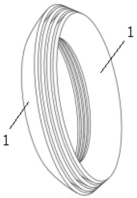
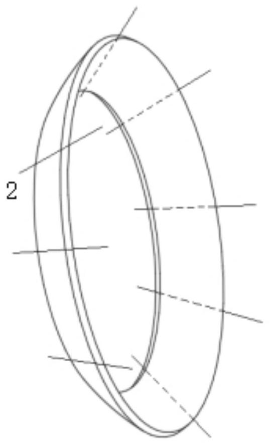
[0042] S1. According to the 3D diagram of the reinforcement, make a 2D expansion diagram, such as Figure 1-2 Shown, and mark the cutting part, such as image 3 As shown, the carbon fiber prepreg is manually cut according to the size of the process design and marked one by one; the carbon fiber volume content of the reinforcement is 65%; as Figure 4 As shown, the inner and outer surfaces of the reinforcement are partly made of 3k carbon fiber satin fabric, and the inside is made of 3k unidirectional prepreg, and the prepreg is epoxy resin type;

[0043] S2. Lay-up design for carbon fiber composite flexible joint reinforcements. The ratio of large mouth, middle section and small mouth is 1:2:1, and each part overlaps and overlaps without obvious boundaries; in the large mouth...

Embodiment 2

[0050] The present embodiment adopts a kind of composite material reinforcement molding process method, and described composite material is carbon fiber / epoxy resin type, comprises the following steps:

[0051] S1. According to the 3D diagram of the reinforcement, make a 2D expansion diagram, such as Figure 1-2 Shown, and mark the cutting part, such as image 3 As shown, the carbon fiber prepreg is manually cut according to the size of the process design and marked one by one; the carbon fiber volume content of the reinforcement is 65%; as Figure 4 As shown, the inner and outer surfaces of the reinforcement are made of 12k carbon fiber plain fabric, and the interior is made of 1k unidirectional prepreg, and the prepreg is epoxy resin type;

[0052] S2. Lay-up design for carbon fiber composite flexible joint reinforcements. The ratio of large mouth, middle section and small mouth is 1:2:1, and each part overlaps and overlaps without obvious boundaries; in the large mouth, mi...

Embodiment 3

[0058] The present embodiment adopts a kind of composite material reinforcement molding process method, and described composite material is carbon fiber / epoxy resin type, comprises the following steps:

[0059] S1. According to the 3D diagram of the reinforcement, make a 2D expansion diagram, such as Figure 1-2 Shown, and mark the cutting part, such as image 3 As shown, the carbon fiber prepreg is manually cut according to the size of the process design and marked one by one; the carbon fiber volume content of the reinforcement is 65%; as Figure 4 As shown, the inner and outer surfaces of the reinforcement part are made of 6k carbon fiber twill fabric, and the inside is made of 3k unidirectional prepreg, and the prepreg is epoxy resin type;

[0060] S2. Lay-up design for carbon fiber composite flexible joint reinforcements. The ratio of large mouth, middle section and small mouth is 1:2:1, and each part overlaps and overlaps without obvious boundaries; in the large mouth, ...


PUM


Abstract

The invention provides a composite material reinforced part and forming process method, The composite material is a carbon fiber / epoxy resin type, and the forming process method comprises the following steps of S1, drawing a 2D expanded drawing according to a 3D drawing of a reinforced part; S2, enabling the carbon fiber composite material flexible joint reinforced part to be subjected to laying design, the proportion of a large opening, a middle section and a small opening is 1 to 2 to 1, all the parts to be overlapped, and no obvious boundary to exist; S3, performing layering angle and sequence design on the carbon fiber composite material flexible joint reinforced part according to four layering angle directions of plus 45 degrees, 0 degree, 90 degrees and minus 45 degrees between the carbon fiber composite material flexible joint reinforced part and the axis; S4, manufacturing a to-be-cured reinforced part by adopting a hot-pressing curing process; S5, carrying out vacuum bag combination on the to-be-cured reinforced part, putting the to-be-cured reinforced part into an autoclave, and heating and curing; and S6, carrying out appearance processing on the cured reinforced part to obtain a required product. According to the process method, targeted design is carried out according to the special stress condition of the flexible joint, the advantage of anisotropy of a carbon fiber composite material is fully utilized, the performance is further improved, and the weight is further reduced.

Description

technical field [0001] The invention belongs to the field of solid rocket motors, and in particular relates to a composite material reinforcement and a molding process method. Background technique [0002] The solid rocket motor has the advantages of good safety, high reliability, good storage performance, high specific impulse density and convenient handling, making it the main power device in the missile field and widely used in the aerospace field. [0003] The flexible nozzle is one of the key components of the solid rocket motor, and it is a device for the energy conversion of the engine and the control of the thrust loss. It is usually composed of a movable body, a fixed body, a flexible joint and an actuator. As the core component of the flexible nozzle, the flexible joint achieves the purpose of nozzle swing through the deformation of the flexible joint. [0004] The flexible joint structure is a thrust vector control executive component composed of four parts: fron...

Claims


Application Information

Patent Timeline
Patent Type & Authority Applications(China)
IPC IPC(8): B29C70/34B29C70/54
CPCB29C70/342B29C70/54Y02T50/40
Inventor 黄驰余威徐节荣廖俊易生平李锐胡铭杰
Owner 湖北航泰科技有限公司
Learn More