Additive manufacturing metal surface strengthening method based on laser shock peening

A technology of laser shock strengthening and metal surface strengthening, which is used in additive manufacturing, additive processing, etc. to achieve the effect of enhancing the lap joint effect, increasing the depth of influence, and ensuring efficiency

Inactive Publication Date: 2021-07-09
湖南珞佳智能科技有限公司
View PDF5 Cites 6 Cited by
  • Summary
  • Abstract
  • Description
  • Claims
  • Application Information

AI Technical Summary

Problems solved by technology

[0005] In view of the above problems, the present invention aims to provide a metal surface strengthening method for additive manufacturing based on laser shock strengthening, which comprehensively solves the ubiquitous problems in the process of laser shock strengthening, such as energy utilization, lap joint effect and depth of influence of residual compressive stress, etc. Using laser-strengthened shock to improve the mechanical properties of materials, improve the residual stress of additive manufacturing, and suppress the generation of defects

Method used


Image

  • Additive manufacturing metal surface strengthening method based on laser shock peening
  • Additive manufacturing metal surface strengthening method based on laser shock peening
  • Additive manufacturing metal surface strengthening method based on laser shock peening

Examples


Embodiment Construction

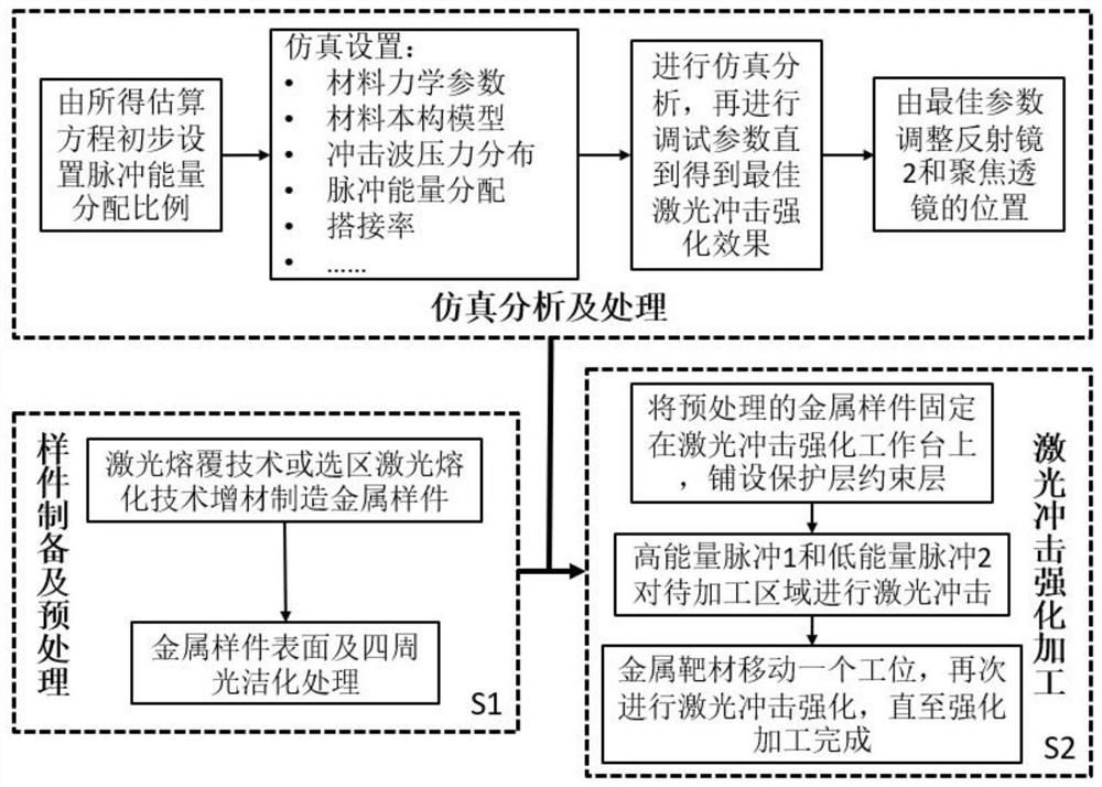
[0033]The invention provides a method for using laser shock to comprehensively improve the mechanical properties of additively manufactured metal surfaces and suppress defects, and at the same time solve the problems of energy utilization, lapping effect and residual stress influence depth that are ubiquitous in the laser shock strengthening process.

[0034] In order to make the purpose, features and advantages of the present invention more obvious and understandable, the technical solutions in the embodiments of the present invention will be clearly and completely described below in conjunction with the accompanying drawings in the embodiments of the present invention. Obviously, the following The described embodiments are only some, not all, embodiments of the present invention. Based on the embodiments of the present invention, all other embodiments obtained by persons of ordinary skill in the art without making creative efforts belong to the protection scope of the present...


PUM

PropertyMeasurementUnit
wavelengthaaaaaaaaaa
diameteraaaaaaaaaa

Abstract

The invention discloses an additive manufacturing metal surface strengthening method based on laser shock peening. The additive manufacturing metal surface strengthening method aims to solve the problems of energy utilization, the lap joint effect, the influence depth of residual compressive stress and the like which commonly exist in the laser shock peening process. The additive manufacturing metal surface strengthening method comprises the steps that firstly, the metal surface manufactured through additive manufacturing is pretreated, and then laser shock peening machining is conducted; simulation treatment and analysis are conducted on the laser shock peening process, the optimal distribution proportion and the light spot lap joint rate of a pulse 1 and a pulse 2 are determined, and the proper mounting positions of a focusing lens and a reflector 2 are adjusted correspondingly; and then a high-energy pulse 1 conducts point-by-point machining strengthening on a to-be-strengthened area, meanwhile, a low-energy pulse 2 conducts pre-machining on a next point-by-point machining area, then a metal target moves by one station, and laser shock peening is conducted again till strengthening machining is completed. According to the additive manufacturing metal surface strengthening method, under the condition that parameters of a laser device are not changed, laser pulse energy is fully utilized, and the laser shock peening effect is comprehensively improved.

Description

technical field [0001] The invention belongs to the technical field of laser shock strengthening in laser processing, and in particular relates to a method for strengthening metal surfaces in additive manufacturing. Background technique [0002] Additive Manufacturing technology (Additive Manufacturing, AM) is a process that accumulates materials layer by layer according to 3D model data and finally forms a real object. Compared with traditional subtractive manufacturing processes, it has no processing restrictions and can manufacture complex items that are difficult to manufacture by traditional processes. The high laser density can also realize the processing of materials that are difficult to process by traditional techniques. It has a wider application range and a higher material utilization rate. Surface roughness, residual stress and various mechanical properties are also difficult to be effectively guaranteed. [0003] Laser Shocking Peening (LSP) is a new type of ma...

Claims


Application Information

Patent Timeline
Patent Type & Authority Applications(China)
IPC IPC(8): C21D10/00C22F3/00B22F10/28B22F10/60B33Y40/20
CPCC21D10/005C22F3/00B22F3/24B33Y40/20
Inventor 李辉申胜男刘胜蔡敏马元琦
Owner 湖南珞佳智能科技有限公司
Why Eureka
Try Eureka