A device and method for measuring return error in surface shape by calibration interferometry

A backhaul error and surface measurement technology, which is applied in the direction of measuring devices, optical devices, instruments, etc., can solve the problems of not being able to meet the high-precision surface shape detection backhaul error elimination, not being able to obtain accurate detection results, and low versatility of backhaul errors. , to achieve the effect of simple structure, short detection cycle and short time consumption

Active Publication Date: 2022-06-28
INST OF OPTICS & ELECTRONICS - CHINESE ACAD OF SCI
View PDF16 Cites 0 Cited by
  • Summary
  • Abstract
  • Description
  • Claims
  • Application Information

AI Technical Summary

Problems solved by technology

[0009] The above-mentioned first method has low versatility for eliminating the backhaul error. For each surface shape measurement, a ray tracing is required. For B j-temp Continue to iterate until W det and W* det are equal, and this method can only perform ray tracing on the sagittal plane and meridian plane, and cannot obtain accurate detection results for non-rotationally symmetrical surfaces to be tested
For the above-mentioned second method, it is considered that there are only return errors with the same value and opposite positive and negative in the interferometric results, and the accuracy is not high, which cannot meet the requirements of high-precision surface shape detection and elimination of return errors.

Method used


Image

  • A device and method for measuring return error in surface shape by calibration interferometry
  • A device and method for measuring return error in surface shape by calibration interferometry
  • A device and method for measuring return error in surface shape by calibration interferometry

Examples


Embodiment Construction

[0035] The specific embodiments of the present invention will be described in detail below with reference to the accompanying drawings.

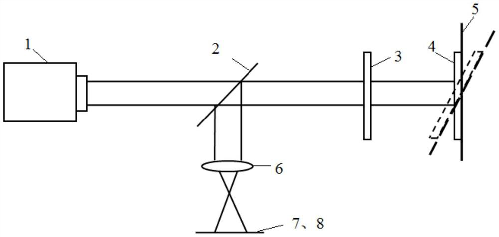
[0036] like figure 1 As shown, a device for calibrating the interferometric measurement of the return error in the surface shape of this embodiment includes:

[0037] Laser 1: Used to generate a high-power, frequency-stabilized laser beam.

[0038] Non-polarizing beam splitter 2: used to transmit the laser beam entering the part of the system where the mirror to be measured is located, and reflect the laser beam exiting to the imaging lens (6).

[0039] Reference lens 3: used to reflect part of the light beam as a reference beam, and transmit part of the light beam to the plane mirror 4. The front surface and the rear surface of the reference lens have a small included angle, and the included angle ranges from 3° to 5°, which can ensure that the reflected light on the front surface does not participate in the formation of interference frin...


PUM


Abstract

The invention discloses a device and a method for measuring a return error in a surface shape by calibration interferometry, belonging to the field of optical detection. This method calibrates the return error of the system by controlling the displacement and deflection of the mirror, and recording the relationship between the spot deviation position and the first 36 order aberration coefficients of the Zernike polynomial. Specifically, the micro-displacement of the mirror is controlled by the five-dimensional electronically controlled micro-displacement stage, so that the light spot reflected by the mirror moves regularly within the field of view, and the relationship between the different light spot positions and the first 36 order aberration coefficients of the Zernike polynomial is recorded, and then the curved surface fit. When the mirror to be tested is placed on the stage, the coefficients of the Zernike polynomial are solved according to the fitted surface by finding the position of the spot, and the return error of the mirror at this position can be obtained by combining the various order aberrations. This method is aimed at the situation that the return error cannot be adjusted to zero during high-precision measurement, and has the advantages of simple structure, high precision and strong practicability.

Description

technical field [0001] The invention relates to the field of advanced optical manufacturing and detection, in particular to a device and method for calibrating interferometry to measure the return error in surface shape. Background technique [0002] In the interferometry, there is a certain aberration in the wavefront to be measured reflected by the mirror to be measured back to the interference system, such as aberration caused by the adjustment and aberration caused by the imperfection of the mirror to be measured, which will lead to the reflection of the mirror to be measured. The light re-enters the interference system at different angles, and the aberration of different magnitudes is caused by the non-common optical path in the interference system, which is called the return error of the interference system. In terms of measuring the plane mirror shape, if the reference mirror and the mirror under test are absolutely parallel, zero fringes will be observed on the detec...

Claims


Application Information

Patent Timeline
Patent Type & Authority Patents(China)
IPC IPC(8): G01B11/24
CPCG01B11/2441G01B21/042
Inventor 刘锋伟邓婷陈强吴永前覃蝶徐淑静
Owner INST OF OPTICS & ELECTRONICS - CHINESE ACAD OF SCI
Why Eureka
Try Eureka