
Device for reducing evaporated condensate and stabilizing urea production and treatment method

A condensate and stable technology, applied in evaporation, separation methods, cascade evaporators, etc., can solve the problem of condensate blocking the lower liquid port and affecting the stable operation of the device, and achieve the improvement of small investment, reasonable structure and convenient use Effect

Active Publication Date: 2021-07-13
新疆心连心能源化工有限公司
View PDF44 Cites 0 Cited by
  • Summary
  • Abstract
  • Description
  • Claims
  • Application Information

AI Technical Summary

Problems solved by technology

[0005] The present invention provides a device and a treatment method for reducing the evaporation of condensate and stable urea production, which overcomes the above-mentioned deficiencies in the prior art, and can effectively solve the existing During the production process of the urea first-stage and second-stage concentration devices, the condensate is prone to block the lower liquid port, which affects the stable operation of the device

Method used


Image

  • Device for reducing evaporated condensate and stabilizing urea production and treatment method
  • Device for reducing evaporated condensate and stabilizing urea production and treatment method
  • Device for reducing evaporated condensate and stabilizing urea production and treatment method

Examples


Embodiment 1

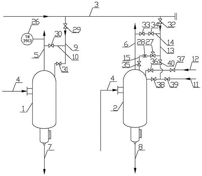
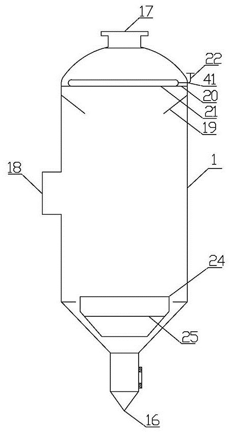
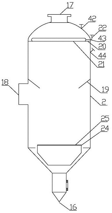
[0023] Embodiment 1: as attached figure 1 As shown, the device for reducing and evaporating condensates to stabilize urea production includes a first-stage evaporative separator 1, a second-stage evaporative separator 2, and a condensate main pipe 3, and the upper inlet of the first-stage evaporative separator 1 and the upper inlet of the second-stage evaporative separator 2 are respectively The urine pipeline 4 is fixedly connected, the top outlet of the first-stage evaporative separator 1 is fixedly connected with a vapor phase pipeline 5, the top outlet of the second-stage evaporative separator 2 is connected with a second vapor phase pipeline 6, and the bottom outlet of the first-stage evaporative separator 1 is fixedly connected with a vapor phase pipeline 5. Evaporation-liquid phase pipeline 7, second-stage evaporation separator 2 bottom outlet is fixedly connected with second evaporation-liquid phase pipeline 8, between the top inlet of first-stage evaporation separator ...

Embodiment 2

[0034] Embodiment 2: as attached figure 1Shown, the treatment method of this device that reduces the evaporating condensate stable urea production is carried out as follows: the urine heated by a steam heater enters the first section of evaporation separator by the feed port 18 on the first section of evaporation separator 1 1, the gas-liquid separation is carried out, the obtained gas phase is exported through a vapor phase pipeline 5, and the obtained liquid phase is sent to the second steam heater by the discharge port 16 after passing through the anti-vortex baffle 24, and the urine heated by the second steam heater is The liquid enters the second-stage evaporation separator 2 from the feed port 18 on the second-stage evaporation separator 2 for gas-liquid separation, the obtained gas phase is output through the second vapor phase pipeline 6, and the obtained liquid phase is output through the second evaporation liquid phase pipeline 6 , when it is necessary to flush the o...


PUM


Abstract

The invention relates to the technical field of urea concentration devices, in particular to a device for reducing evaporated condensate and stabilizing urea production and a treatment method. The device comprises a first-section evaporation separator, a second-section evaporation separator and a condensate header pipe, wherein an upper inlet of the first-section evaporation separator and an upper inlet of the second-section evaporation separator are fixedly communicated with urine pipelines respectively; a top outlet of the first-section evaporation separator is fixedly communicated with a first vapor phase pipeline, and a top outlet of the second-section evaporation separator is fixedly communicated with a second vapor phase pipeline. The device is reasonable and compact in structure, convenient to use and small in improvement investment, the purposes of stabilizing the production process and avoiding granulation stopping are achieved by improving the internal structure of the device, condensation compound formation can be reduced fundamentally by changing part of purging media, the water content of finished urea is not affected, the product quality is guaranteed, and meanwhile, the washing flow can be remotely and automatically controlled, so that the labor intensity of personnel is reduced.

Description

technical field [0001] The invention relates to the technical field of urea concentration devices, and relates to a device and a treatment method for reducing the evaporation of condensate and stabilizing urea production. Background technique [0002] The urea one-stage and two-stage concentration systems use a rising film evaporator. The urine enters the heater from the bottom of the heater, and after being discharged, it enters the evaporation separator through the circumcision method, and the gas-liquid separation is carried out in the separator. The liquid phase goes down through the rotary plate and enters the lower liquid pipe to be discharged, and the gas phase is released from the gas phase pipe of the separator, so as to achieve the purpose of urine concentration. However, during the production process, the gas phase port and the volute in the middle of the second-stage evaporative separator are more likely to form condensate, and the condensate falls off and blocks...

Claims


Application Information

Patent Timeline
Patent Type & Authority Applications(China)
IPC IPC(8): B01D1/00B01D1/30
CPCB01D1/0082B01D1/0088B01D1/30Y02P20/141
Inventor 谷雨刘志鹏孔秋福王皓孟祥进付祥喜吕印贺
Owner 新疆心连心能源化工有限公司
Learn More