Shear wall frame and shear wall

A shear wall and frame technology, which is applied to walls, building components, ceramic molding machines, etc., can solve the problem that the performance needs to be further improved, and achieve the effect of stable shear wall frame structure, increasing bearing capacity, and increasing ultimate strength.

Pending Publication Date: 2021-07-16
HEFEI UNIV OF TECH +1
View PDF0 Cites 3 Cited by
  • Summary
  • Abstract
  • Description
  • Claims
  • Application Information

AI Technical Summary

Problems solved by technology

[0003] However, the existing steel plate concrete composite shear wall has a simple structure, and its performance needs to be further improved.

Method used


Image

  • Shear wall frame and shear wall
  • Shear wall frame and shear wall
  • Shear wall frame and shear wall

Examples


Embodiment Construction

[0048] Glossary:

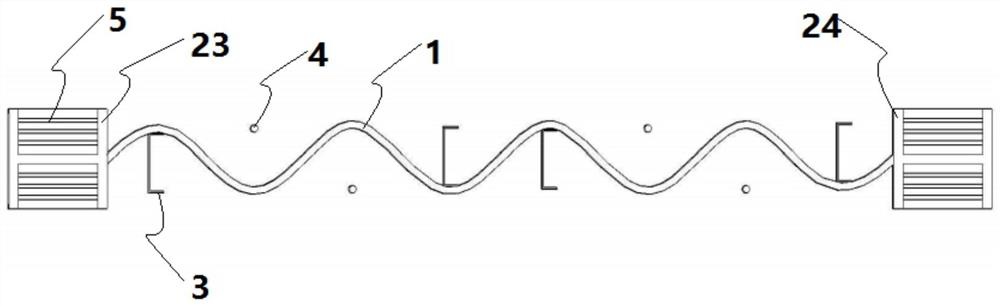
[0049] The central plane of the corrugated plate 1 is the middle plane of the crest surfaces on both sides of the corrugated plate 1, and the crest surfaces on both sides of the corrugated plate 1 are as follows image 3 As shown in P1, the central plane of corrugated plate 1 is as follows image 3 Shown in P0; specifically, the positions from the central plane P0 to the peak planes P1 on both sides are equal, and the central plane P0 and the peak planes P1 are parallel to each other.

[0050] shear wall frame

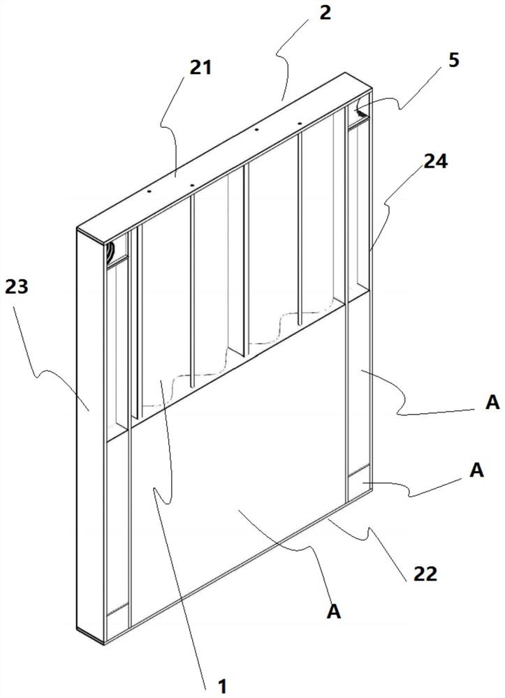
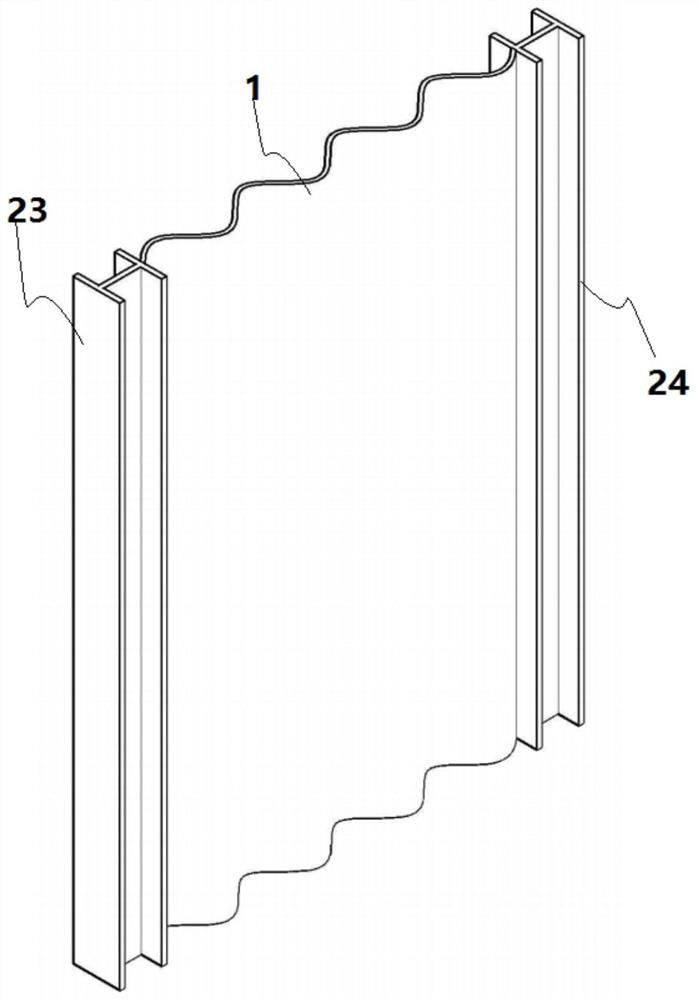
[0051] A shear wall frame proposed in this embodiment includes: a corrugated plate 1 , a frame 2 and a shear member 3 , the corrugated plate 1 is arranged on the inner periphery of the frame 2 and the edges of the corrugated plate 1 are connected to the frame 2 .

[0052] Any surface of the corrugated plate 1 has concave parts and convex parts arranged alternately. A plurality of shearing elements 3 are distributed on both sides of the corrugated ...


PUM


Abstract

The invention provides a shear wall frame. The shear wall frame is characterized in that the shear wall frame comprises a corrugated plate, a frame and shear pieces. The corrugated plate is arranged on the inner periphery of the frame, and the edges of the corrugated plate are connected with the frame. Concave parts and convex parts which are alternately arranged are arranged on any surface of the corrugated plate. The multiple shear pieces are distributed on the two sides of the corrugated plate, and all the shear pieces are connected with the corrugated plate and arranged in the different concave parts. The corrugated plate and the frame form a main body structure of the shear wall frame, when the shear wall is vibrated, the surface of the corrugated plate obliquely intersects with vibration perpendicular to the central plane of the corrugated plate, the wave crest firstly encounters vibration force, the oblique crossing angle of the vibration force of the wave crest of the corrugated plate perpendicular to the central plane of the corrugated plate is small, and the bearing capacity of the shear wall is improved.

Description

technical field [0001] The invention relates to the field of civil and structural engineering, in particular to a shear wall frame and a shear wall. Background technique [0002] Shear wall is an important lateral force-resisting member commonly used in high-rise structures. According to the construction method, it can be divided into reinforced concrete shear wall, steel plate shear wall and steel plate concrete composite shear wall. Among them, reinforced concrete shear wall is the most It is common, but its large size and heavy weight will cause premature failure under the action of earthquake load. The steel plate shear wall is small in size, light in weight and has high bearing capacity, but the wall is thin and prone to instability and damage, and the steel structure is exposed to the environment, which is easy to rust and corrode, and has poor durability. Partially wrapped composite shear wall (PEC) is based on the steel plate shear wall, and the two sides of the ste...

Claims


Application Information

Patent Timeline
Patent Type & Authority Applications(China)
IPC IPC(8): E04B2/56E04B1/98E04H9/02E04B1/76E04B1/94E04B1/64B28B1/16B28B1/50
CPCB28B1/16B28B1/50E04B1/64E04B1/76E04B1/94E04B1/98E04B2/56E04H9/02
Inventor 王静峰何卫东刘用沈奇罕王波沈万玉田朋飞张坤徐秋雨陶书庆
Owner HEFEI UNIV OF TECH
Why Eureka
Try Eureka