Method for improving noise reduction effect of low-frequency noise reduction acoustic backing of pipeline and acoustic backing

A technology for noise reduction and pipelines, applied in the direction of pipe components, pipes/pipe joints/pipes, mechanical equipment, etc., can solve the problems of no airflow environment, resonance sound absorption frequency dependent, sound absorption material escape, etc., to achieve enhanced noise reduction. Noise effect, widening noise frequency band, increasing runner length effect

Active Publication Date: 2021-07-16
ZHUZHOU TIMES NEW MATERIALS TECH
View PDF3 Cites 1 Cited by
  • Summary
  • Abstract
  • Description
  • Claims
  • Application Information

AI Technical Summary

Problems solved by technology

In order to solve the above problems, based on the principle of the Helmholtz resonator, people have used micro-perforated plates as noise reduction linings, and left a cavity with a certain depth behind them. The air layer in the back cavity forms a resonance effect to effectively absorb sound. Because the micro-perforated plate is generally made of metal, it has high strength and anti-aging, so it is suitable for environments with high airflow, high vibration, and high wind pressure, which makes up for the absorption of porous materials. However, the noise reduction frequency band of the micro-perforated plate is generally narrow, and the micro-perforated plate is usually thin. In order to improve the rigidity and strength of the overall structure, it is necessary to install structures such as honeycomb tubes and quadrilateral grids behind the micro-perforated plate. The back cavity is divided into tube-type air columns. The entrance of each air column is a plurality of micro-holes on the micro-perforated plate. The sound absorption frequency of the acoustic lining formed by the micro-perforated plate is related to the pore size , perforation rate, plate thickness, and the depth of the cavity behind the micro-perforated plate. Among them, the cavity depth plays a decisive role. The greater the cavity depth, the lower the resonant sound absorption frequency. However, in actual engineering, due to the Due to the size limitation, the total height available for installing the acoustic lining is also limited, which leads to the inability to achieve the required lower resonant sound absorption frequency even with the maximum cavity depth, thus failing to meet the requirements of low-frequency noise reduction
[0004] In the prior art, for example, the Chinese patent with the patent number "CN201420251826.0" and the patent name "Low Frequency Sound Absorbing Structure" includes a micro-perforated plate facing the side of the sound source, the micro-perforated plate is opposite to the back plate, surrounded by The side plate connects the two, and between the micro-perforated plate and the back plate is the back cavity where the air layer is located. The disadvantages are: 1. It is only suitable for static, that is, no airflow environment; 2. Only through the aperture, perforation rate and plate The resonant sound absorption frequency is designed for parameters such as thickness that have little influence, and the design range is very small, and the resonant sound absorption frequency still mainly depends on the depth of the existing cavity
Another example is the Chinese patent with the patent number "CN201911043642.9" and the patent name "A Ultra-Thin Multi-absorption Peak Low-Frequency Sound Absorber", which includes a perforated cover plate, embedded round holes, a spiral partition, and a non-porous baffle. Plate, bottom plate and one or more perforated baffles have the following disadvantages: 1. There is only one hole on the perforated cover plate. Compared with the micro-perforated plate with multiple holes per unit area, its sound absorption capacity per unit area is poor ;2. The structure is flat and plate-shaped, not suitable for the inner wall of the pipe with arc surface
Another example is that the patent number is "CN201720202289.4", and the patent name is "A sound-absorbing module suitable for airflow environment", which includes a protective surface layer, a filter layer, a medium-high frequency sound-absorbing layer and a low-frequency sound-absorbing layer. The existing deficiencies include: 1. There are about 2 / 3 of the area without openings, and the sound absorption capacity per unit area is poor; 2. The sound-absorbing material used in it has the risk of escaping under high-speed airflow; Easy to block holes, not anti-aging, poor strength, not resistant to high-speed airflow and other defects

Method used


Image

  • Method for improving noise reduction effect of low-frequency noise reduction acoustic backing of pipeline and acoustic backing
  • Method for improving noise reduction effect of low-frequency noise reduction acoustic backing of pipeline and acoustic backing
  • Method for improving noise reduction effect of low-frequency noise reduction acoustic backing of pipeline and acoustic backing

Examples


Embodiment 1

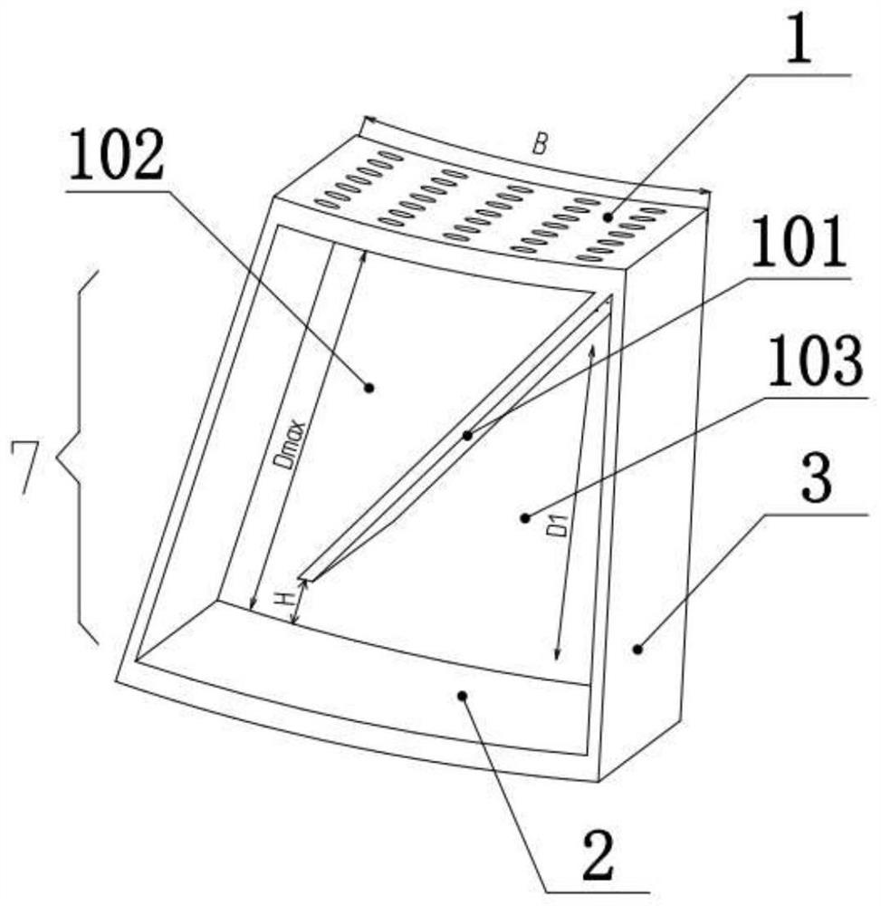
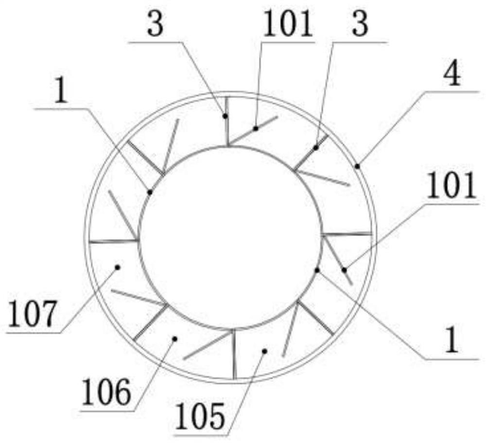
[0048] Such as figure 1 As shown, the acoustic lining to improve the noise reduction effect of the pipeline low-frequency noise reduction lining includes a micro-perforated plate 1 and a sound-absorbing cavity tube 7; the sound-absorbing cavity tube 7 includes a back plate 2 set opposite to the micro-perforated plate 1, and the micro-perforated plate 1 and the back plate 2 are connected by side plates 3; there are four side plates 3 in total, which are two side plates 3 relatively arranged in the length direction of the micro-perforated plate 1 and the back plate 2, and two side plates 3 relatively arranged in the micro-perforated plate 1 and the back plate 2. The two side plates 3 in the width direction of the plate 1 and the back plate 2, in order to facilitate the display of the structure in the cavity of the sound-absorbing unit, the two side plates 3 in the width direction of the micro-perforated plate 1 and the back plate 2 are not shown in the drawings Out; the back pla...

Embodiment 2

[0053] The difference between this embodiment and Embodiment 1 is that: Figure 4 As shown, a second partition plate 201 and a ninth partition plate 202 are also arranged in the second small lumen tube 103, and one end of the second partition plate 201 is fixed on the back plate 2, and the second partition plate 201 The other end is a free end; one end of the ninth dividing plate 202 is fixedly connected to the right side plate 3, and the other end of the ninth dividing plate 202 is fixedly connected to the first dividing plate 101; the second dividing plate 201 and The ninth partition plate 202 separates the second small lumen 103 into a third small lumen 203 and a fourth small lumen 204 . Through the above arrangement, the flow channel length of the noise in the second small lumen tube 103 is increased by setting the second partition plate 201 in the second small lumen tube 103, as Figure 5 As shown, the increased flow path length is the dotted line S; and by setting the n...

Embodiment 3

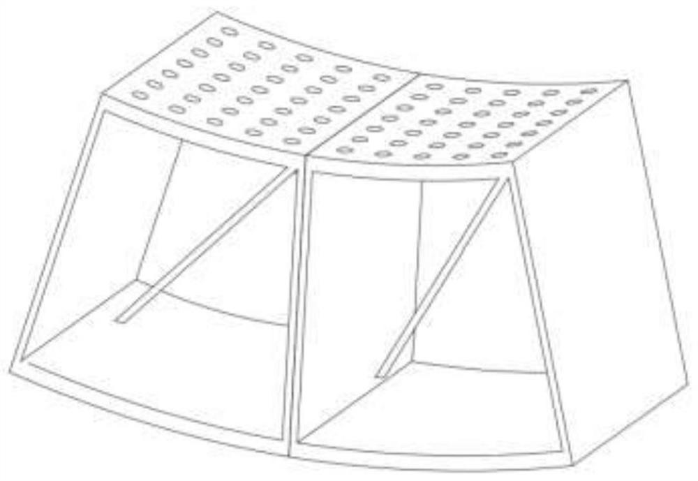
[0056] as attached Figure 7 As shown, the difference between the present embodiment and the second embodiment is that the sound-absorbing unit is radially superimposed toward the inner wall of the pipe, and the superposition of the two acoustic linings is the middle plate 6, which also adopts the micro-perforated plate 1 material production. When the noise enters the fourth sound-absorbing unit 601 from the holes of the micro-perforated plate 1, part of the noise stays in the fourth sound-absorbing unit 601 for noise reduction according to the method of Embodiment 2, and the other part of the noise flows downward into the fifth sound-absorbing unit 601. The sound-absorbing unit 602 performs noise reduction according to the method of the second embodiment, so that the sound-absorbing unit can expand the sound-absorbing frequency range within a limited installation height range, making the entire sound lining applicable to a wider range of scenarios.

[0057] Such as Figure ...


PUM

PropertyMeasurementUnit
Installation heightaaaaaaaaaa
Apertureaaaaaaaaaa
Thicknessaaaaaaaaaa

Abstract

The invention relates to the technical field of pipeline noise reduction, in particular to a method for improving the noise reduction effect of a low-frequency noise reduction acoustic backing of a pipeline and the acoustic backing. The noise reduction effect is improved by additionally arranging a partition plate to increase the flow channel length of noise entering a cavity of a sound absorption unit of the acoustic backing. According to the technical scheme, the acoustic backing structure for prolonging the depth of the cavity of the sound absorption unit can be designed within the limited acoustic liner installation height range, the resonance sound absorption frequency band is effectively widened, the sound absorption capacity on the unit area cannot be reduced, the overall noise reduction amount is guaranteed, the acoustic backing structure can be installed on the inner walls of pipelines in various shapes, the pneumatic profile requirement is met, wind resistance is not increased, and air flow is not reduced.

Description

technical field [0001] The invention relates to a method for improving the noise reduction effect of a pipeline low-frequency noise reduction lining and an acoustic lining, belonging to the technical field of pipeline noise reduction. Background technique [0002] Pipeline noise refers to the noise generated by vibration, internal medium flow friction, collision or disturbance when the pipeline is running, such as the noise in central air-conditioning pipelines, gas pipelines, ventilation pipelines, and the intake and exhaust noise of industrial equipment such as blowers and engines etc. These noises not only bring harm to the equipment itself, but also seriously affect people's physical and mental health. Therefore, it is necessary to take corresponding noise reduction measures to control them. [0003] At present, it is a conventional and effective noise reduction measure to install an acoustic lining (a noise reduction structure) on the inner wall of a rigid pipe to turn ...

Claims


Application Information

Patent Timeline
IPC IPC(8): F16L55/033
CPCF16L55/033
Inventor 颜猛查国涛傅亮郭福林杨涛周常荣贺才春
Owner ZHUZHOU TIMES NEW MATERIALS TECH
Why Eureka
Try Eureka