Vehicle brake-by-wire system and braking method thereof

A brake-by-wire and vehicle technology, applied in the direction of braking transmission, braking action starting device, brake, etc., can solve the problems of inability to realize active braking, high production cost, complex structure of the braking system, etc., and achieve high reliability. performance, small working current, and simplified braking system

Active Publication Date: 2021-07-23
南京经纬达汽车科技有限公司
View PDF8 Cites 8 Cited by
  • Summary
  • Abstract
  • Description
  • Claims
  • Application Information

AI Technical Summary

Problems solved by technology

However, with the continuous development and popularization of automotive electronics, intelligence, and new energy vehicle technology, the traditional hydraulic braking system can no longer meet the development requirements of automobiles, and the development of new multifunctional hydraulic braking systems will face great challenges.
[0003] At present, the smart cars on the market are mainly electric cars. The active braking requirements of chassis active control systems such as adaptive cruise control and electronic stability programs of smart cars, among them, active braking refers to when the driver does not step on the brake. In the case of pedals, all or part of the wheels can still be braked; the traditional hydraulic brake system is vacuum assisted, but there is no vacuum source on the smart car, and another vacuum source is needed to meet the functions of the traditional hydraulic brake system The demand makes it difficult for the traditional hydraulic braking system to implement active braking, which makes the structure of the braking system complex and the production cost is high. It is difficult to apply the traditional hydraulic braking system to smart cars, and it is impossible to realize the active braking function

Method used


Image

  • Vehicle brake-by-wire system and braking method thereof

Examples


Embodiment 1

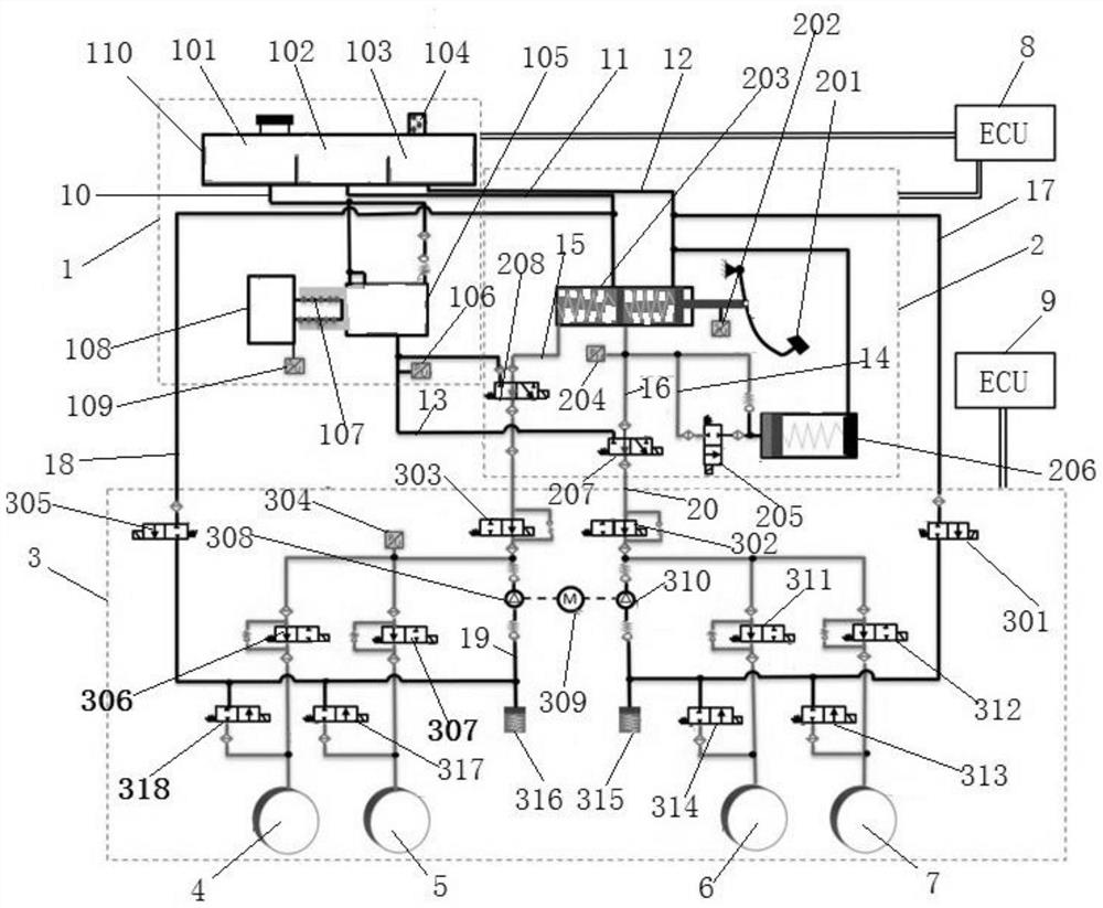
[0059] As shown in the figure, a vehicle brake-by-wire system of the present invention includes an electric cylinder servo assembly 1, a pedal simulation unit 2, a hydraulic control unit 3, a first controller 8 and a second controller 9, wherein:

[0060] The electric cylinder servo assembly 1 is used to deliver brake fluid to the hydraulic control unit to establish the required braking pressure (provide braking force in the control-by-wire braking mode or active braking mode) according to the operation command, which includes a fluid storage tank 110 , servo motor 108 and electric cylinder 105, the servo motor 108 is connected with the electric cylinder 105 through the transmission device 107, a current sensor is installed on the servo motor 108, used to measure the current of the servo motor, in the liquid storage tank 110 Divided into a first liquid storage chamber 101, a second liquid storage chamber 102 and a third liquid storage chamber 103, the first liquid storage chamb...

Embodiment 2

[0075] On the basis of Embodiment 1, a braking method using the vehicle brake-by-wire system of Embodiment 1 of the present invention includes the following braking control:

[0076] (1) Brake-by-wire mode (the default braking system of the vehicle):

[0077] According to the instructions of the upper controller, the brake-by-wire mode is selected. In this brake-by-wire mode, the pedal stroke sensor 202 is used to detect the stroke of the driver's pedal depression, and the collected pedal displacement signal (depression depth of the pedal) is sent to the The first controller 8, the first controller controls the operation of the servo motor according to the collected pedal displacement signal;

[0078] The first controller controls the first two-position three-way solenoid valve 207, and the second two-position three-way solenoid valve energizes 208 to open (the sixth brake between the first two-position three-way solenoid valve 207 and the manpower cylinder 203 at this moment)...


PUM


Abstract

The invention discloses a vehicle brake-by-wire system and a braking method thereof. The system comprises: an electric cylinder servo assembly which is used for conveying brake fluid to a hydraulic control unit according to an operation instruction to establish required brake pressure; a pedal simulation unit used for detecting the displacement of a pedal to simulate the brake pedal feeling and conveying brake fluid to the hydraulic control unit according to the operation instruction so as to realize manual backup braking; a hydraulic control unit used for providing brake pressure for each brake wheel cylinder according to the brake instruction; a first controller used for detecting and selecting a braking mode and sending an operation instruction to the electric servo cylinder assembly and the pedal simulation unit; and a second controller used for sending a braking instruction to the hydraulic control unit, and electrically connected with the hydraulic control unit. The brake-by-wire system has the functions of brake-by-wire and active braking, has high reliability of a traditional brake-by-wire system, can simulate pedal feeling, and also has the active braking function of an intelligent automobile; and the pressure is easy to control, and the pressure adjusting precision is high.

Description

technical field [0001] The invention belongs to the technical field of braking systems, in particular to a vehicle-by-wire braking system and a braking method thereof. Background technique [0002] Automobiles have become an indispensable means of transportation for people to travel, and good braking performance is the primary guarantee for safe driving of automobiles. Conventional hydraulic braking systems are able to meet the braking needs of conventional internal combustion engine vehicles. However, with the continuous development and popularization of automobile electronics, intelligence and new energy vehicle technology, the traditional hydraulic braking system can no longer meet the development requirements of automobiles, and the development of new multifunctional hydraulic braking systems will face great challenges. [0003] At present, the smart cars on the market are mainly electric cars, and the active braking requirements of chassis active control systems such a...

Claims


Application Information

Patent Timeline
Patent Type & Authority Applications(China)
IPC IPC(8): B60T13/14B60T13/68B60T13/74B60T8/40B60T7/04
CPCB60T13/141B60T13/686B60T13/745B60T8/409B60T7/042
Inventor 邓伟文赵蕊丁能根
Owner 南京经纬达汽车科技有限公司
Why Eureka
Try Eureka