Copper slag dilution-reduction integrated furnace

A depletion and integrated technology, applied in the field of copper slag depletion-reduction integrated furnace, to achieve the effect of promoting reduction, strengthening dispersion distribution, and reducing copper content

Pending Publication Date: 2021-07-23
NORTHEASTERN UNIV +1
View PDF6 Cites 0 Cited by
  • Summary
  • Abstract
  • Description
  • Claims
  • Application Information

AI Technical Summary

Problems solved by technology

In the copper slag reduction process, there is no application

Method used


Image

  • Copper slag dilution-reduction integrated furnace

Examples


Embodiment 1

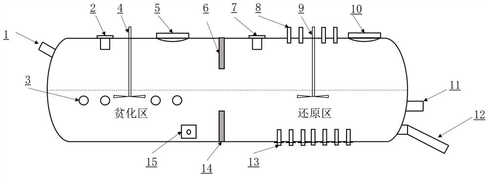
[0035] A copper slag depletion-reduction integrated furnace, the schematic diagram of which is shown in figure 1 ; Including the dilution system and the reduction system, the dilution system and the reduction system are connected in series and separated by a retaining wall, the retaining wall is an upper retaining wall and a lower retaining wall; the upper retaining wall is connected to the top of the copper slag depletion-reduction integrated furnace , the lower retaining wall is connected to the bottom of the copper slag depletion-reduction integrated furnace, and the channel between the upper retaining wall and the lower retaining wall is the depleted slag inlet of the reduction system; the retaining wall separates the copper slag depletion-reduction integrated furnace into The depleted area and the reduced area, the depleted slag generated in the depleted area flows into the reduced area by way of overflow after passing through the retaining wall.

[0036] The depletion sy...

Embodiment 2

[0047] A kind of copper slag depletion-reduction integrated furnace, same as embodiment 1;

[0048] Its operation includes the following steps:

[0049] Using molten copper slag, in which FeS 2 The amount added is 8% of the copper slag mass. The constant temperature depletion time is 35min, and the speed of the mechanical stirrer in the depletion zone is controlled at 110rpm; an excess of 50% of coke and calcium oxide is added to the reduction zone, the stirring speed in the reduction zone is 100rpm, and the reduction time is 45min. molten iron.

Embodiment 3

[0051] A kind of copper slag depletion-reduction integrated furnace, same as embodiment 1;

[0052] Its operation includes the following steps:

[0053] Using the above copper slag, in which FeS 2 The amount added is 8% of the copper slag mass. The constant temperature depletion time is 35min, and the speed of the mechanical stirrer in the depletion zone is controlled at 90rpm; an excess of 40% of coke and calcium oxide is added to the reduction zone, the stirring speed in the reduction zone is 90rpm, and the reduction time is 30min. molten iron.


PUM


Abstract

The invention discloses a copper slag dilution-reduction integrated furnace, and belongs to the field of comprehensive utilization of copper slag. The copper slag dilution-reduction integrated furnace comprises a dilution system and a reduction system which are separated by a retaining wall, and a dilution area furnace body of the dilution system is provided with a molten copper slag feeding port, a dilution agent feeding port, a copper matte outlet and a dilution area smoke outlet; dilution area oxygen-enriched fuel injection systems are arranged on the two sides of the dilution area furnace body; a dilution area vortex stirring device is arranged in the dilution area furnace body; and a slag former feeding opening, a slag outlet, a copper-containing molten iron outlet and a reduction area smoke outlet are arranged on a reduction area furnace body of the reduction system, a reducing agent feeding spray gun is arranged at the bottom of the reduction area furnace body, a reduction area oxygen-enriched fuel injection system is arranged at the top of the reduction area furnace body, and a reduction area vortex stirring device is arranged in the reduction area furnace body. According to the furnace body, valuable components of copper and iron in the copper slag can be efficiently recycled, high-valued slag-free 100% utilization is achieved, and meanwhile synergistic utilization of waste heat of the copper slag is achieved.

Description

technical field [0001] The invention relates to the field of comprehensive utilization of copper slag, in particular to a copper slag depletion-reduction integrated furnace. Background technique [0002] Copper slag is an important by-product in the process of copper pyrometallurgy, which contains a considerable amount of valuable metal resources such as Cu, Fe, and Ni. The modern copper smelting process has carried out the treatment of depleting and recovering copper to the copper slag. However, there are still many defects in the device for depleting copper slag and recovering copper. For example, the application number 201811300235.7 discloses "a device and method for continuously depleting copper smelting slag," which includes two parts. The first part is slag buffering. process, the second part is the slag flow depletion process. The high-temperature molten copper slag from the copper smelting furnace is directly introduced into the buffer device, and then heated and ...

Claims


Application Information

Patent Timeline
IPC IPC(8): C22B7/04C22B15/00C21B11/00
CPCC22B7/04C22B7/002C22B15/0054C22B15/0052C21B11/00Y02P10/20
Inventor 张廷安豆志河吕国志韩继标刘燕张子木赫冀成
Owner NORTHEASTERN UNIV
Why Eureka
Try Eureka