Centrifugal hydrogen circulating pump

A circulating pump and centrifugal technology, which is applied in the field of centrifugal hydrogen circulating pumps, can solve the problems of poor sealing, noise, etc., and achieve the effects of small voltage difference, easy uniform diffusion, and prevention of obstruction

Active Publication Date: 2021-07-23
BEIJING BOLKEN EQUIP +1
View PDF6 Cites 5 Cited by
  • Summary
  • Abstract
  • Description
  • Claims
  • Application Information

AI Technical Summary

Problems solved by technology

[0006] The German company Busch is famous for its production of claw compressors and vacuum pumps. On this basis, it has developed a claw-type low-flow hydrogen circulation pump, which is driven by a high-speed DC brushless motor. The surface of the rotor and the shell of the compressor are coated with Layer protection, which has been applied to a variety of hydrogen fuel cell vehicles, has the advantages of high reliability and compact structure, but it needs to design a better tooth shape of the claw pump to balance the compression ratio and performance; its disadvantage is due to its oil-free The principle of gap sealing is adopted under the conditions, so the sealing performance is poor; in addition, the noise and vibration of the claw booster pump are also problems that need to be solved

Method used


Image

  • Centrifugal hydrogen circulating pump
  • Centrifugal hydrogen circulating pump
  • Centrifugal hydrogen circulating pump

Examples


Embodiment Construction

[0033] In order to facilitate understanding of the present invention, below in conjunction with Figure 1-7 And specific examples, the present invention is described in more detail.

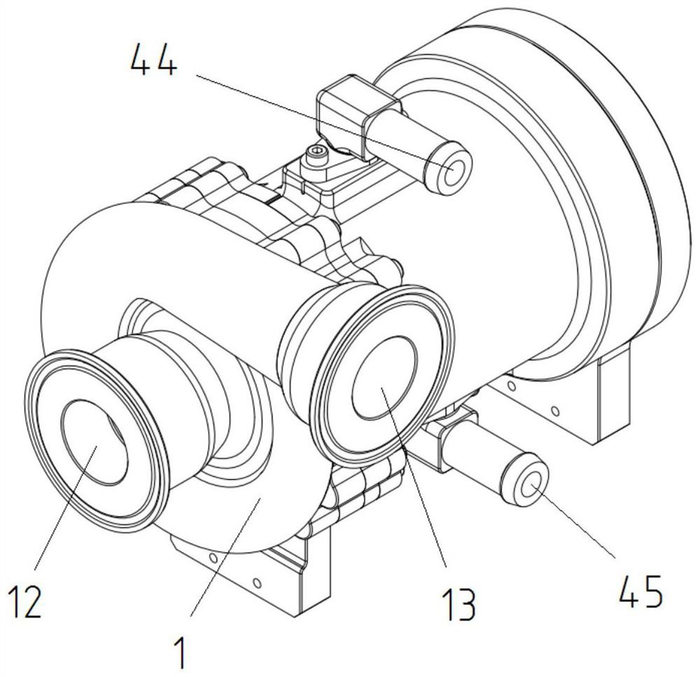
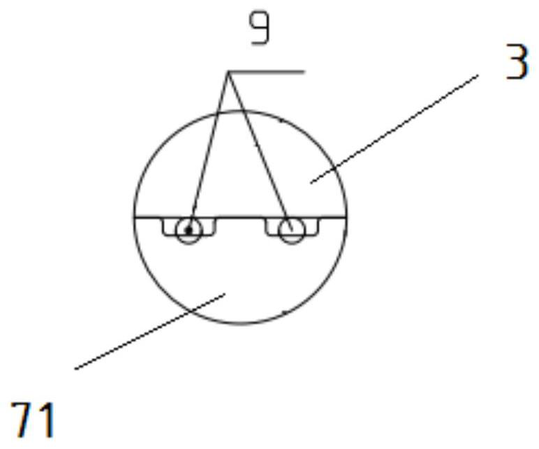
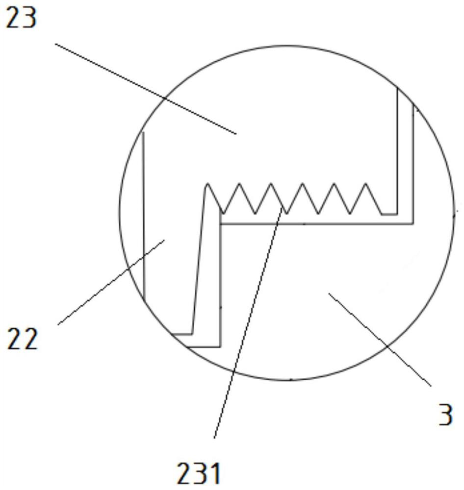
[0034] A centrifugal hydrogen circulation pump, such as Figure 1-4 As shown, it includes a volute 1, an impeller 2, an adapter seat 3, a pump casing 4, and a motor stator 5 and a motor rotor 6 located inside the pump casing 4; the volute 1 includes a The axial air inlet 12 and the tangential exhaust pipe 13 arranged in its circumferential direction are sealed with a sealing ring 9 (such as an O-ring) between the volute 1 and the adapter seat 3 to prevent hydrogen leakage. Driven by the rotor shaft 61, the impeller 2 accelerates and pressurizes the gas at the axial inlet 12 and then discharges it from the tangential exhaust pipe 13; the adapter seat 3 is close to the One end of the volute 1 is sequentially provided with an impeller housing hole and a bearing steel sleeve housing hole, the impel...


PUM


Abstract

The invention discloses a centrifugal hydrogen circulating pump. The pump comprises a volute, an impeller, an adapter, a pump shell, a motor stator and a motor rotor; and the volute comprises an axial air inlet formed in the center of the volute and a tangential exhaust pipe arranged in the circumferential direction of the volute, and the impeller is driven by the rotating shaft to accelerate and pressurize air and then exhaust the air from the tangential exhaust pipe. According to the pump, the impeller and the rotating shaft are connected to the adapter in a floating and suspended mode through a ceramic bearing and a bearing steel sleeve, and an O-shaped sealing ring is arranged between the bearing steel sleeve and the adapter, so that sealing is effectively achieved, and vibration caused by unbalance of the rotor and high-frequency and low-frequency excitation caused by unsteady flowing of airflow in the rotor are avoided; the flow requirement of a high-power fuel cell system with the power of 60 kW or above can be met; and aiming at the characteristic that the humidity and temperature change range of a working medium in a complex multi-phase medium environment is relatively large, the obstruction of flow field accumulated water on airflow is effectively prevented, the output current density of a cell is improved, and the stability of the output voltage of the hydrogen fuel cell is kept.

Description

[0001] The invention relates to the technical field of fuel cell power systems, in particular to a centrifugal hydrogen circulation pump. Background technique [0002] As a truly "zero-emission" clean energy, the application of hydrogen fuel cells in automobiles is developing rapidly. Hydrogen fuel cells use electrochemical reactions instead of combustion (gasoline, diesel) or energy storage (battery). Combustion releases pollutants like COx, NOx, SOx gas and dust. A hydrogen fuel cell, on the other hand, only produces water and heat. If the hydrogen is produced by renewable energy sources (photovoltaic panels, wind power, etc.), the entire cycle is a complete process that does not generate harmful emissions. The hydrogen fuel cell runs quietly, with a noise of only about 55dB. This makes hydrogen fuel cells suitable for indoor installations, or outdoors where noise is restricted. That is, hydrogen fuel cells have the advantages of no pollution, no noise, and high efficien...

Claims


Application Information

Patent Timeline
Patent Type & Authority Applications(China)
IPC IPC(8): F04D17/10F04D25/06F04D29/02F04D29/059F04D29/063F04D29/08F04D29/28F04D29/30F04D29/42F04D29/58
CPCF04D17/10F04D25/06F04D29/023F04D29/059F04D29/063F04D29/083F04D29/284F04D29/30F04D29/4206F04D29/584F04D29/5853
Inventor 徐子介肖育民徐焕恩赵洪洋张璇
Owner BEIJING BOLKEN EQUIP
Why Eureka
Try Eureka