
System for dead steam recovery and shaft heating and method

A technology of exhaust steam recovery and wellbore, which is applied in the system and system field of exhaust steam recovery and heating wellbore, which can solve the problems of short service life of traps, poor return water, and large number of traps, so as to achieve recovery and utilization, Increased release speed and simple system structure

Pending Publication Date: 2021-07-23
SHENHUA SHENDONG COAL GRP
View PDF0 Cites 0 Cited by
  • Summary
  • Abstract
  • Description
  • Claims
  • Application Information

AI Technical Summary

Problems solved by technology

In addition, due to the large number of steam traps in the direct steam heating system, and the short service life of the steam traps, it is difficult to maintain them in place, which further increases the amount of steam entering the condensate pipe network
This part of exhaust steam is generally discharged to the air, and a lot of heat is lost, and the water loss is also relatively large.
[0006] (2) The air in winter is generally relatively dry. After the air entering the shaft is heated by the hot air supplied by the heater room, the air in the shaft and the air inlet is extremely dry. To heat and reduce dust, multiple channels are installed in the shaft and the air inlet The water curtain is sprayed to reduce dust, but it still cannot be completely suppressed
[0007] (3) After the exhausted steam enters the return water pipe, a mixture of steam and water is formed in the return water pipe, which may easily cause poor return water, resulting in blockage of the steam heating circuit in some areas

Method used


Image

  • System for dead steam recovery and shaft heating and method

Examples


specific Embodiment approach

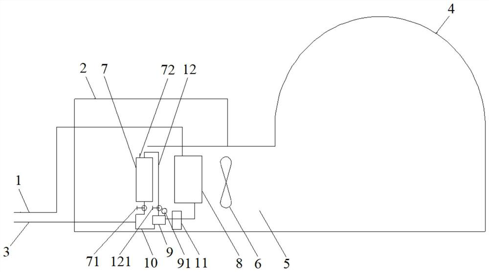
[0098] There are three air intake shafts in Shangwan Coal Mine Industrial Plaza, which are the main inclined shaft, the first sub-level tunnel, and the second sub-level tunnel, and there are three heater rooms respectively. The steam boiler about 500m away from the air inlet shaft supplies steam to the heater room through the steam inlet pipe. The air is sucked into the heater room by the fan. The bottom outlet of the steam heat exchanger is returned to the condensed water collection tank of the boiler room through the condensed water pipe, and a large amount of exhaust steam in the condensed water is discharged to the atmosphere from the exhausted steam exhaust pipe at the top of the condensed water collected water tank. Every heating season, a large amount of exhausted steam is evacuated to form fog clouds and light rain. This not only causes waste of heat and water in exhaust steam, but also has adverse effects on the atmosphere.

[0099] instead use as figure 1 After the...


PUM


Abstract

The invention discloses a system for dead steam recovery and shaft heating and a method. The system comprises a steam inlet pipe, an air heating machine room, a condensate pipe, an air inlet shaft and an air heating duct; a dead steam heat exchanger, a steam heat exchanger, a fan, a dead steam release box, a drain valve and a dead steam conveying pipeline are sequentially arranged in the air heating machine room; the steam inlet pipe penetrates into the air heating machine room and is connected to a top inlet of the steam heat exchanger; a feeding hole of the dead steam release box is connected to a bottom outlet of the steam heat exchanger; the drain valve is arranged on a pipeline from the bottom outlet of the steam heat exchanger to the feeding hole of the dead steam release box; the two ends of the dead steam conveying pipeline are connected to a steam phase outlet of the dead steam release box and a top inlet of the dead steam heat exchanger; the water inlet end of the condensate pipe is connected to a liquid phase outlet of the dead steam release box and a bottom outlet of the dead steam heat exchanger, and the water outlet end of the condensate pipe penetrates out of the air heating machine room; and the air heating machine room communicates with the air inlet shaft through the air heating duct. According to the system and the method, dead steam in the condensate pipeline can be released and used for heating the shaft, and the dead steam is recycled.

Description

technical field [0001] The invention belongs to the field of coal mining, and in particular relates to a system and a system for exhaust steam recovery and shaft heating. Background technique [0002] It is common to use steam for heating in northern coal mine industrial sites, and the heating method is generally the coexistence of steam heating and hot water heating. On the user side of steam heating, single units with large heat loads such as plant heating and air intake shafts are generally heated directly by steam; places with small heat loads such as office buildings, apartments, and living areas use steam-water heat exchange for heating. Water heating. [0003] The air inlet shaft is generally a flat or inclined shaft. A heater room is set near the wellhead, and the heater room is composed of a steam radiator, a fan and a warm air duct. After the steam enters from the top of the steam radiator through the pipeline, it releases heat and turns into condensed water, wh...

Claims


Application Information

Patent Timeline
IPC IPC(8): F24D15/00F24H3/06F28B1/02F28B9/08F28B11/00
CPCF24D15/00F24H3/06F28B1/02F28B9/08F28B11/00
Inventor 周成军雷鸣哲郭瑶李莉
Owner SHENHUA SHENDONG COAL GRP
Learn More