Vehicle-mounted positioning antenna and vehicle glass
A technology for positioning antennas and vehicle glass, which is applied to antennas, antennas, antenna parts and other directions suitable for movable objects, and can solve the problems of antenna performance degradation, increase of vehicle wind resistance, large size of positioning antennas, etc., and achieve wide performance Good, low production cost, effect of reducing interference
- Summary
- Abstract
- Description
- Claims
- Application Information
AI Technical Summary
Problems solved by technology
Method used
Image
Examples
Embodiment 1
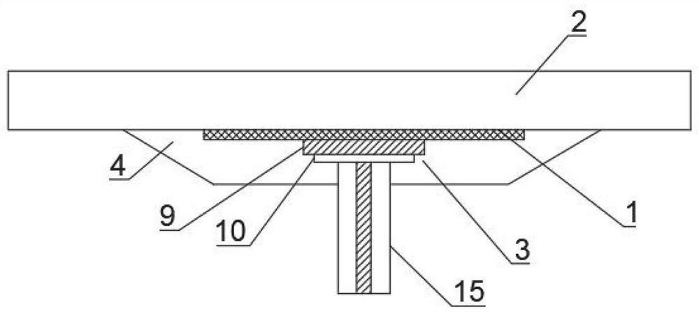
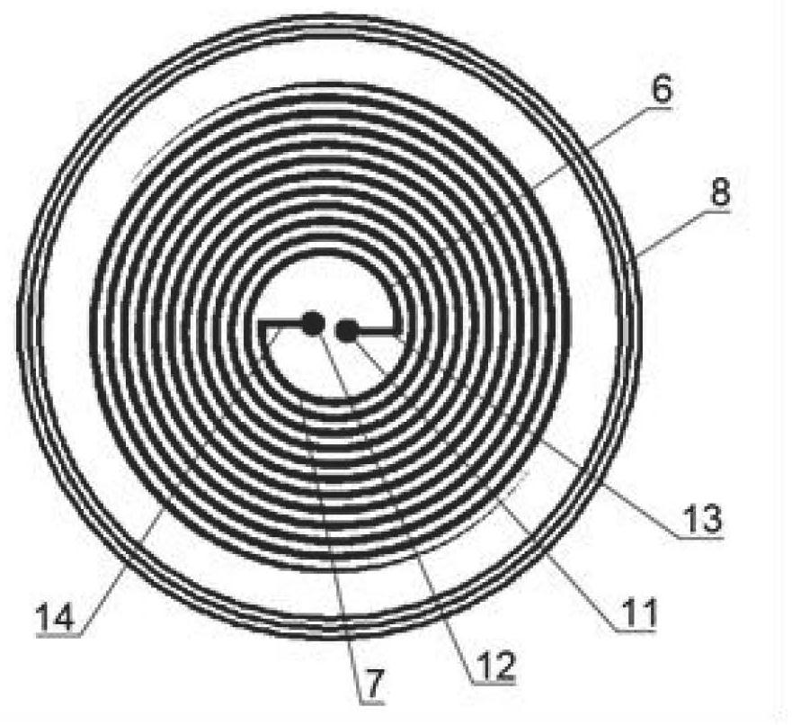
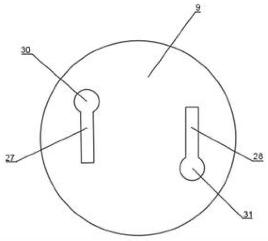
[0060] Such as figure 1 As shown, the embodiment of the present invention provides a positioning antenna applied to a vehicle, including an antenna unit 1 for receiving and transmitting positioning signals, and the antenna unit 1 can be arranged on a substrate 2 in a printing manner (not limited thereto), The antenna unit 1 is electrically connected to the feeder 3, and the feeder 3 is electrically connected to the control device. The control device is used to exchange position information with the outside world through the antenna unit 1. The control device is an existing CPU, single-chip microcomputer, etc., which can perform signal processing The device, and the connection mode of the feeding device 3 is also the prior art, and the structure diagram will not be repeated here; the back side of the substrate 2 is provided with a reflection cavity 4, and the projection of the antenna unit 1 towards the back of the substrate 2 is located in the reflection cavity 4 That is, when...
Embodiment 2
[0066] Such as Figure 4 As shown, the main difference from Embodiment 1 is that the antenna unit 1 is arranged on the front surface of the substrate 2, and the feeding device 3 also includes a ground plate 16 arranged on the back surface of the substrate 2; it can be understood that the antenna unit 1 can also be It is embedded in the substrate 2, that is, embedded in the substrate 2 (such as a laminated board). In order to better protect the antenna unit 1 . A cover 29 may be provided on the antenna unit 1, and the cover 29 is made of a material that can protect the antenna unit 1 but does not block electromagnetic waves, such as resin. Such as Figure 5As shown, the ground plate 16 is provided with a fifth slit 17 and a sixth slit 18, the shape of the fifth slit 17 and the sixth slit 18 is a broken line, preferably the fifth slit 17 and the sixth slit 18 are in the shape of a 90° broken line , the fifth patch 19 and the sixth patch 20 are respectively arranged on its two...
Embodiment 3
[0069] Such as Figure 6 As shown, the main difference from Embodiment 1 and Embodiment 2 is that the feeding device 3 includes a flexible circuit board 21, and the flexible circuit board 21 is an FPC board, and the material constituting the flexible circuit board 21 includes but is not limited to LCP (Industrial liquid crystal polymer), MPI (modified polyimide), PI (polyimide) and other materials. Such as Figure 7 As shown, a balun structure 22 is provided on the flexible circuit board 21, the head end of the balun structure 22 is electrically connected to the first feeder 13 and the second feeder 14 respectively, and its terminal is electrically connected to the control device through the coaxial feeder 15; Such as Figure 8 As shown, the terminals of the first helical arm 6 and the second helical arm 7 are tapered, that is, the gradual structure with gradually reduced width, thereby reducing the terminal reflection of the current on the first helical arm 6 and the second...
PUM
 Abstract
Description
Claims
Application Information
 - R&D
- Intellectual Property
- Life Sciences
- Materials
- Tech Scout
- Unparalleled Data Quality
- Higher Quality Content
- 60% Fewer Hallucinations
Browse by: Latest US Patents, China's latest patents, Technical Efficacy Thesaurus, Application Domain, Technology Topic, Popular Technical Reports.
© 2025 PatSnap. All rights reserved.Legal|Privacy policy|Modern Slavery Act Transparency Statement|Sitemap|About US| Contact US: help@patsnap.com


