
Microwave pulse generation device and method based on time domain mode-locked optoelectronic oscillator

An optoelectronic oscillator and a technology for generating methods, which are applied in the structure/shape of optical resonators, lasers, laser parts and other directions, can solve the problems of difficult radio frequency pulse signals and difficult to realize repetition frequency tunable radio frequency pulse signals, etc. The effect of high carrier frequency microwave pulse signal generation and low phase noise

Active Publication Date: 2021-07-23
UNIV OF ELECTRONICS SCI & TECH OF CHINA
View PDF11 Cites 5 Cited by
  • Summary
  • Abstract
  • Description
  • Claims
  • Application Information

AI Technical Summary

Problems solved by technology

The main problem of passively mode-locked optoelectronic oscillators is that the repetition frequency of the RF pulse signal is determined by the length of the ring cavity of the optoelectronic oscillator. It is difficult to achieve a higher repetition rate when the length of the ring cavity is increased to reduce the phase noise. Radio frequency pulse signal generation, and the structure is difficult to achieve repeat frequency tunable radio frequency pulse signal generation

Method used


Image

  • Microwave pulse generation device and method based on time domain mode-locked optoelectronic oscillator
  • Microwave pulse generation device and method based on time domain mode-locked optoelectronic oscillator
  • Microwave pulse generation device and method based on time domain mode-locked optoelectronic oscillator

Examples


Embodiment 1

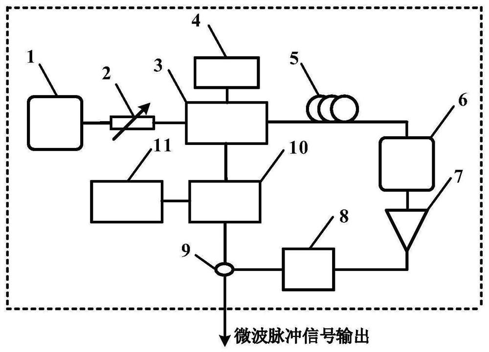
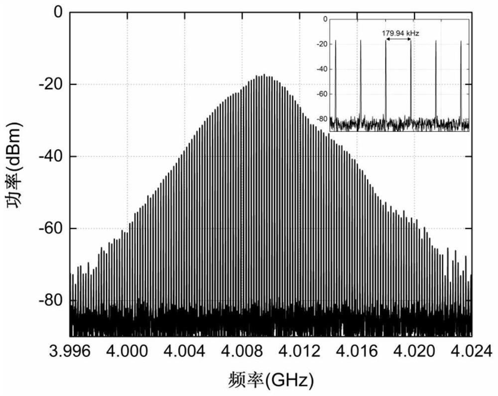
[0044] according to figure 1 As shown in the structure, active mode-locking technology is used to realize microwave pulse generation based on time-domain mode-locked optoelectronic oscillator. In the experimental system, the DC light source uses a DFB laser with a center wavelength of 1560nm and an output power of 17dBm. The adjustable optical attenuator 2 adopts a knob type, the operating bandwidth of the electro-optical intensity modulator 3 is 20 GHz, and the length of the single-mode optical fiber 5 is 1.1 km. The analog bandwidth of the photodetector 6 is about 15 GHz, the operating frequency range of the electrical amplifier 7 is 2 GHz-18 GHz, and the gain is about 25 dB. The center frequency of the electrical filter 8 is about 4GHz, its 3dB bandwidth is 70MHz, and the working frequency range of the electrical modulator 10 is 15MHz-18GHz. In the experiment, a spectrum analyzer is used to test the spectrum characteristics of the output microwave pulse signal of the pres...

Embodiment 2

[0048] When setting Ω=N×Δf FSR And when N≥2, the present invention can realize the harmonic mode-locked photoelectric oscillator. Similar to Example 1, at first according to figure 1 The connection system shown, the devices used in the experiment are the same as those in Example 1. The difference is that the frequency of the sinusoidal signal output by the function generator 11 is set to Ω=359.88kHz, satisfying Ω=2×Δf FSR , and then realize the harmonic mode-locked optoelectronic oscillator. Therefore, in Embodiment 2, the repetition frequency of the generated microwave pulse signal is twice the free spectral range of the resonator. Figure 6 shows the frequency spectrum of the microwave pulse signal generated by the harmonic mode-locked photoelectric oscillator measured when the spectrum analyzer is set to Span=30MHz and RBW=5kHz, and image 3 Compared to that, the frequency spacing of the signal increases. Also set the sampling rate of the high-speed real-time oscillosco...


PUM


Abstract

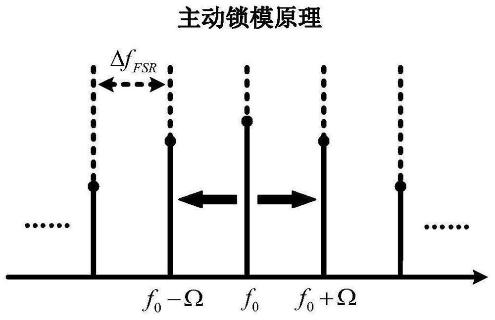
The invention discloses a microwave pulse generation device and method based on a time domain mode-locked optoelectronic oscillator, and relates to the technical field of photoelectricity. The microwave pulse generation device comprises a direct-current laser, a variable optical attenuator, an electro-optic intensity modulator, a direct-current power supply, a single-mode optical fiber, a photoelectric detector, an electric amplifier, an electric filter, an electric power divider, an electric modulator and a function generator. The electric modulator driven by an external electric signal is introduced into a photoelectric oscillation loop, a time-domain active mode-locking photoelectric oscillator is constructed, and phase locking between longitudinal modes in a cavity is realized, so that multi-mode oscillation is realized, and a high-carrier-frequency microwave pulse signal with low phase noise is generated. By setting the frequency of the external electric signal, the repetition frequency of the output microwave pulse signal can be changed.

Description

technical field [0001] The invention relates to the field of optoelectronic technology, in particular to a microwave pulse generation device and method based on a time-domain mode-locked optoelectronic oscillator. Background technique [0002] Due to the low phase noise and tunable frequency of the microwave signal generated by the optoelectronic oscillator, it has potential application value in many fields such as radar, communication, and testing. The output signal of a traditional optoelectronic oscillator is oscillated by intracavity noise. There are uncertain phase relationships and gain competition between modes, and stable multi-mode oscillation cannot be achieved. Therefore, it is difficult to generate broadband microwave signals, and only single-frequency microwave signals can be generated. With the rapid development of radar and communication technology, the demand for broadband microwave signals is increasing. Therefore, combining the advantages of high frequency ...

Claims


Application Information

Patent Timeline
IPC IPC(8): H01S3/11H01S3/08H01S3/10
CPCH01S3/10053H01S3/08022H01S3/10H01S3/1109Y02D30/70
Inventor 曾珍章令杰张旨遥张尚剑李和平刘永
Owner UNIV OF ELECTRONICS SCI & TECH OF CHINA
Learn More