Coated die for use in hot stamping

A hot stamping and coating technology, applied in the direction of forming tools, manufacturing tools, sputtering coating, etc., can solve the problems of hardness reduction, reduction, change, etc., and achieve excellent wear resistance and seizure resistance.

Active Publication Date: 2021-07-23
HITACHI METALS LTD
View PDF12 Cites 0 Cited by
  • Summary
  • Abstract
  • Description
  • Claims
  • Application Information

AI Technical Summary

Problems solved by technology

The TRD method or CVD method is used to treat the mold at a temperature close to the quenching temperature of the steel base material and then temper (partially quenched again before that), but deformation of the mold may occur due to high temperature treatment. or size change issues
In addition, these treatments are repeatedly used, but since the TRD method or the CVD method uses carbon in the steel material of the mold base material to form a film, if repeated treatments are performed, the carbon near the surface of the mold will decrease, which may cause Decrease in hardness or decrease in adhesion to the film

Method used


Image

  • Coated die for use in hot stamping
  • Coated die for use in hot stamping
  • Coated die for use in hot stamping

Examples


Embodiment 1

[0048] First, the aggregation resistance was evaluated by simulating the initial stage of hot stamping.

[0049] As for the base material, prepare the base material of high-speed steel SKH51 (21mm×17mm×2mm) after mirror grinding, degreasing and cleaning, and set the prepared base material in the arc ion of the structure in which the base material rotates at the center surrounded by multiple targets in the plating device. For the target for a1 layer, use Al 60 Cr 37 Si 3 As the target, a vanadium target was used as the target for the a2 layer. Thereafter, as an initial step, after heating and degassing the substrate at 450° C. in the apparatus, Ar gas was introduced to perform plasma cleaning treatment (Ar ion etching) on ​​the surface of the substrate.

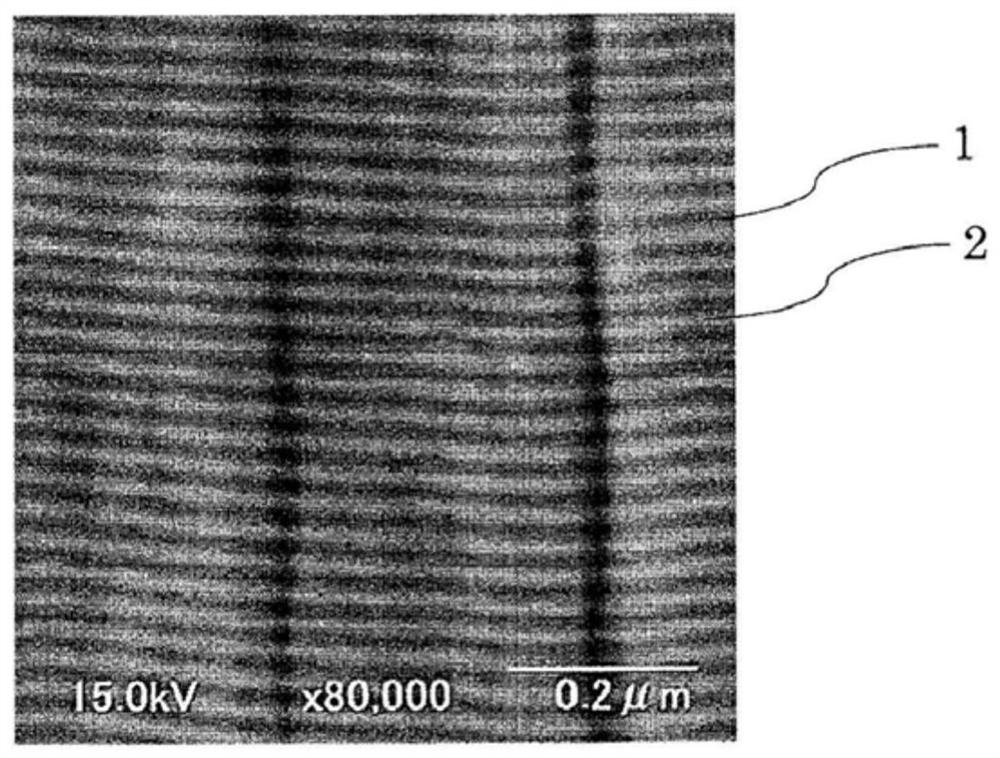
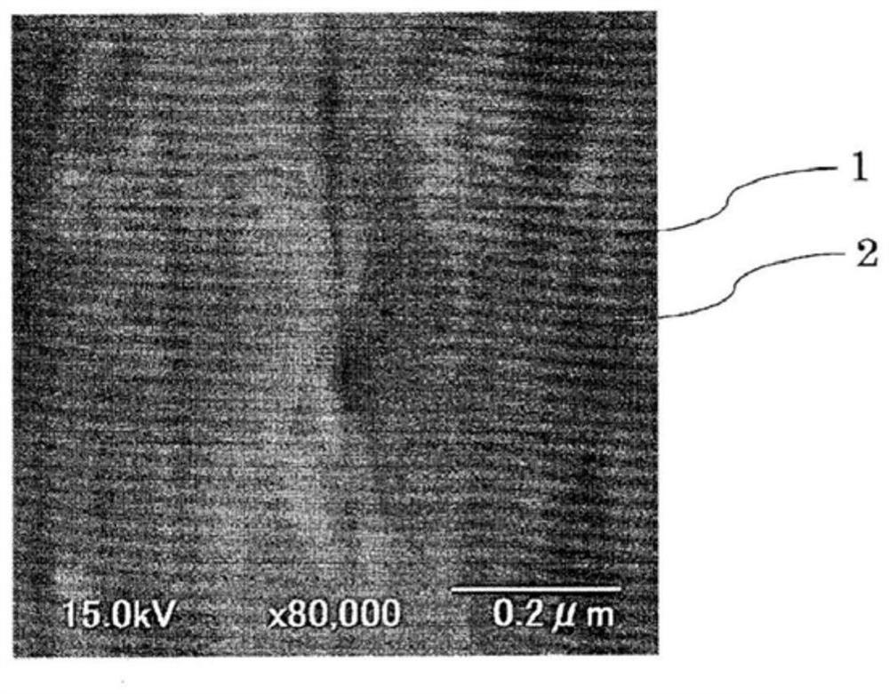
[0050] Next, the base material after the plasma cleaning treatment was coated while introducing nitrogen gas, and Sample No. 1 and Sample No. 2 were prepared. Sample No. 1 and Sample No. 2 both formed a film (alternate la...

Embodiment 2

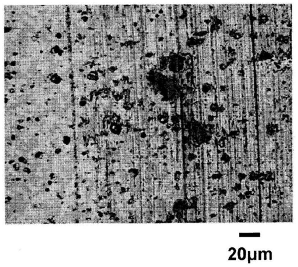
[0053] Next, wear resistance was evaluated by simulating the middle stage of hot stamping. In addition to sample No.1 and sample No.2 of Example 1, the samples to be evaluated were further adjusted to AlCrSiN: 19nm, VN: 10nm (ta2 / ta1=0.52), and the total film of the alternate lamination part The thickness is set to 19 μm, and the other manufacturing method is the same as that of sample No. 1. Sample No. 3 and the alternate lamination of AlCrSiN and CrN that do not contain V as a comparative example (alternative lamination of AlCrSiN: 23 nm, CrN: 26 nm, total Sample No. 4 with a thickness of 4.1 μm). A ball-on-disk tester (tribometer (Tribometer) manufactured by CSM Instruments) was used in the test. As for the test environment, a pin made of matrix high speed steel (a mirror-polished hemisphere with a tip diameter of 6mm and a hardness of 64HRC) was placed under a load of 10N on one side in an atmosphere of 400°C assuming the mid-term processing of hot stamping. ) is pressed...


PUM

PropertyMeasurementUnit
thicknessaaaaaaaaaa
tensile strengthaaaaaaaaaa
thicknessaaaaaaaaaa

Abstract

The purpose of the present invention is to provide a coated die which, used in hot stamping, has both adhesion resistance in the initial processing stage and abrasion resistance in the intermediate processing stage. This coated die for use in hot stamping comprises a hard film on the work surface, wherein the hard film has an alternating layer section formed by alternating lamination of a1 layers, formed from nitride in which the metal portion including semimetals are at least 30% chromium by atomic ratio, and a2 layers, formed from nitride in which the metal portions including semimetals are at least 50% vanadium by atomic ratio. Defining ta1 and ta2 as the thickness of the a1 layers and the a2 layers respectively, and defining the film thickness ratio Xb as the film thickness ratio ta2 / ta1 of a1 layers and a2 layers adjacent to each other in the substrate-side region of the alternating layer section and the film thickness ratio Xt as the film thickness ratio ta2 / ta1 of a1 layers and a2 layers adjacent to each other in the outermost region of the alternating layer section, it holds that Xt > Xb.

Description

technical field [0001] The present invention relates to a coated mold covered with a hard film applied to a mold for hot stamping. Background technique [0002] Conventionally, in plastic working such as forging and press working, steels such as tool steels such as cold work die steels, hot work die steels, and high-speed steels, or cemented carbide alloys are used as base materials. In plastic working using such a die for press working or forging, since the working surface of the die slides against the workpiece, the working face of the die tends to suffer from wear and loss such as seizure, and it is desired to increase the life of the die. In particular, bending dies or drawing dies are subject to high forming pressure, and are prone to bite due to the sliding of the workpiece and the die. The term "occlusion" as used herein refers to the formation of a chemically active surface on either or both of the working surfaces of members that slide against each other, which is ...

Claims


Application Information

Patent Timeline
Patent Type & Authority Applications(China)
IPC IPC(8): B21D37/01
CPCB21D37/01B21D22/022C23C28/04C23C28/40C23C28/42C23C28/44C23C8/80C23C8/22C23C8/26C23C14/0641C23C28/34
Inventor 庄司辰也
Owner HITACHI METALS LTD
Why Eureka
Try Eureka