Multi-aperture laser system

A technology of optical systems and laser beams, applied in the field of optical systems, can solve problems that hinder the practical utilization of increased power

Pending Publication Date: 2021-07-23
ACTIVE FIBER SYST GMBH
View PDF0 Cites 0 Cited by
  • Summary
  • Abstract
  • Description
  • Claims
  • Application Information

AI Technical Summary

Problems solved by technology

Moreover, power-limiting effects occur, such as ionization in gas-filled hollow fibers or Kerr nonlinearities in air or substrates, which actually prevent the practical utilization of increased power

Method used


Image

  • Multi-aperture laser system
  • Multi-aperture laser system
  • Multi-aperture laser system

Examples


Embodiment Construction

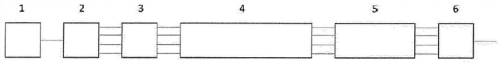
[0038] exist figure 1 In the exemplary embodiment of , the input laser beam from the laser source 1 is divided into N channels. For this purpose, an arrangement of cascade-arranged partial mirrors or polarizing beam splitters, a diffractive element or an arrangement of mirrors with regions of different reflectivity (see below) can be used as splitting element 2 for this. The N spatially separated sub-beams are now each spatially amplified by the optical amplifier 4 . For this, classical single amplifiers (e.g. fiber-based amplifiers) or one or more multicore fibers can be used, which implement the concept of spatially separated amplification in a compact manner. Ideally, the necessary optical path length adjustment element 3 for controlling coherent combining is located in the beam path after the splitting element 2 and before the optical amplifier 4 . For this, piezoelectric elements, such as EOMs or optical wedges movable by actuators are possible.

[0039] If the system ...


PUM


Abstract

The invention relates to an optical system having a dividing element (2) which divides the input laser beam (EL) into a number of spatially separate sub-beams, at least one optical amplifier (4), through which the spatially separate sub-beams propagate, at least one path-length adjustment element (3), which adjusts the path length of at least one of the sub-beams, and a combination element (6, 8), which coherently superimposes the sub-beams in an output laser beam. The invention addresses the problem of achieving high beam quality of the output laser beam, and reducing the requirements of the surface quality of the used optical components as compared to the prior art. To this end, the invention proposes that at least one optical functional element (5, 5', 6', 7) from the group of transport element, spectral broadening element, beam deflection element, optical isolator, optical modulator and pulse compressor is provided, which functional element is arranged after the at least one optical amplifier (4) in the beam path, and through which functional element the spatially separate sub-beams propagate.

Description

technical field [0001] The invention relates to an optical system having the following characteristics: [0002] - a splitting element that splits the input laser beam into a number of spatially separated sub-beams, [0003] - at least one optical amplifier through which the spatially separated sub-beams propagate, [0004] - at least one optical path length adjusting element, which adjusts the optical path length of at least one sub-beam, and [0005] - A combining element coherently superimposing the sub-beams in the output beam. Background technique [0006] The performance of optical components, such as laser amplifiers, spectral broadening elements, transmission fibers, optical devices (such as mirrors, substrates, lenses), etc., is limited by various physical effects. A distinction should be made here between average power and pulse peak power, which is important in pulsed systems. The limitation is due to thermal effects, which occur above a certain average power ...

Claims


Application Information

Patent Timeline
Patent Type & Authority Applications(China)
IPC IPC(8): H01S3/00H01S3/23H01S3/067H01S3/13
CPCG02B27/1093G02B27/145H01S3/005H01S3/0057H01S3/0071H01S3/0092H01S3/06737H01S3/1307H01S3/2308H01S3/2383H01S3/06716H01S3/06758
Inventor B·利姆珀特A·凯兰克T·艾达姆
Owner ACTIVE FIBER SYST GMBH
Why Eureka
Try Eureka