Centrifugal equipment and centrifugal method

A technology of centrifugal equipment and centering seat, which is applied in auxiliary molding equipment, ceramic molding machines, manufacturing tools, etc., can solve the problems of increasing equipment manufacturing cost and manufacturing difficulty, low service life of support wheels, and low service life of accessories, and achieves The effect of reducing the complexity of the mechanical structure, prolonging the service life and improving production efficiency

Active Publication Date: 2021-07-27
JIANGSU TANGCHEN MACHINERY EQUIP MFG
View PDF6 Cites 1 Cited by
  • Summary
  • Abstract
  • Description
  • Claims
  • Application Information

AI Technical Summary

Problems solved by technology

[0004] 1) The centrifugation process of concrete products is the process of solid-liquid separation. The uneven distribution of solid and liquid during centrifugation will lead to severe vibration of the pipe mold, and the low precision of equipment processing and installation will also aggravate the vibration of the pipe mold. The hard contact between the mold and the support wheel will lead to a low service life of the support wheel when the mold is centrifugal. In order to improve this situation, it is often necessary to continuously improve the performance of the support wheel, shaft and other accessories, which will greatly increase the manufacturing capacit

Method used


Image

  • Centrifugal equipment and centrifugal method
  • Centrifugal equipment and centrifugal method
  • Centrifugal equipment and centrifugal method

Examples


Example Embodiment

[0062] The technical scheme of the present invention will be described in further detail below in conjunction with the accompanying drawings and specific embodiments, so that those skilled in the art can better understand the present invention and implement it, but the examples given are not intended to limit the present invention.

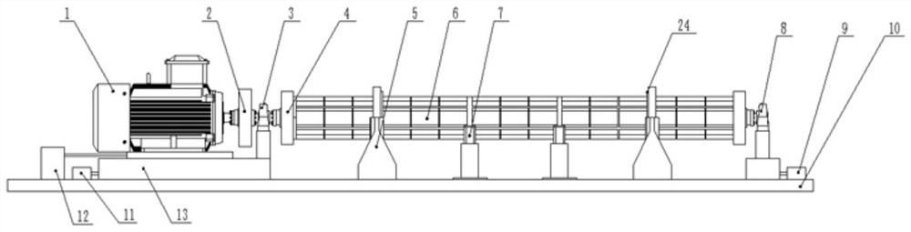
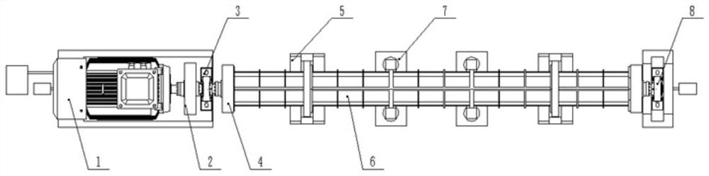
[0063] like Figure 1-21 As shown, a centrifugal device includes a main drive device 1 for providing a power source and a mold 6 for providing a centrifugal working cavity. The present invention takes a concrete product mold as an example. There is a cavity in the mold 6 for storing The solid-liquid mixture of concrete products, it should be noted that the mold 6 includes an upper mold and a lower mold structure, see Figure 1-2 As shown, the centrifugal device also includes a magnetic bearing seat 5, a first centering seat and a second centering seat, wherein the mold 6 is arranged on the magnetic bearing seat 5 and the mold body 22 of the mold 6...


PUM


Abstract

The invention discloses centrifugal equipment and a centrifugal method. The centrifugal equipment comprises a main driving device used for providing a power source and a mold used for providing a centrifugal working containing cavity, and further comprises a magnetic bearing block, a first centering block and a second centering block, wherein the mold is arranged on the magnetic bearing block, a permanent magnet ring corresponding to the magnetic bearing block is arranged on a mold body of the mold, one end of the mold is connected to an output shaft of the main driving device through the first centering block, and the other end of the mold is connected to the second centering block. The centrifugal equipment adopts a magnetic suspension centrifugal mode, the permanent magnet ring is arranged on the mold body, a magnetic bearing structure is located at the mold supporting position, and compared with a traditional ball bearing, a sliding bearing and an oil film bearing, the magnetic bearing has the characteristics of being small in mechanical abrasion, low in energy consumption, small in noise, long in service life, free of lubrication and free of oil pollution due to the fact that mechanical contact does not exist.

Description

technical field [0001] The invention relates to a centrifugal device and a centrifugal method. Background technique [0002] A centrifuge is a machine that uses centrifugal force to separate components in a mixture of liquid and solid particles or liquid and liquid. It is widely used in chemical, petroleum, food, pharmaceutical, mineral processing, coal, water treatment and shipbuilding and other departments. For the centrifugal process of pipe pile products, in the existing design, the centrifuge is driven by a motor, and the speed of the pipe mold is adjusted through the deceleration and frequency conversion speed regulating device, so as to realize the centrifugation of the pipe mold at various speeds (different products have different centrifugal Process parameters), wherein, the centrifuge equipment has a parallel shaft structure, the parallel shaft is equipped with conventional bearings, the bearing seat is connected to the base through bolts, the support wheel structu...

Claims


Application Information

Patent Timeline
IPC IPC(8): B28B21/30B28B21/82B28B21/80B28B17/00
CPCB28B21/30B28B21/82B28B21/80B28B17/00Y02P70/10
Inventor 杜苏林
Owner JIANGSU TANGCHEN MACHINERY EQUIP MFG
Why Eureka
Try Eureka