
Hydraulic device for feeding back output torque of power assisting servo motor by utilizing self-weight potential energy

A technology of servo motor and output torque, which is applied in the field of servo motor to achieve the effect of increasing output torque, strengthening auxiliary output capability, and reducing consumption frequency

Active Publication Date: 2021-07-27
深圳市科斯腾液压设备有限公司
View PDF9 Cites 0 Cited by
  • Summary
  • Abstract
  • Description
  • Claims
  • Application Information

AI Technical Summary

Problems solved by technology

[0004] The purpose of the present invention is to provide a hydraulic device that uses self-weight potential energy feedback to assist the output torque of the servo motor to solve the related problems raised in the above-mentioned background technology

Method used


Image

  • Hydraulic device for feeding back output torque of power assisting servo motor by utilizing self-weight potential energy
  • Hydraulic device for feeding back output torque of power assisting servo motor by utilizing self-weight potential energy
  • Hydraulic device for feeding back output torque of power assisting servo motor by utilizing self-weight potential energy

Examples


Embodiment 1

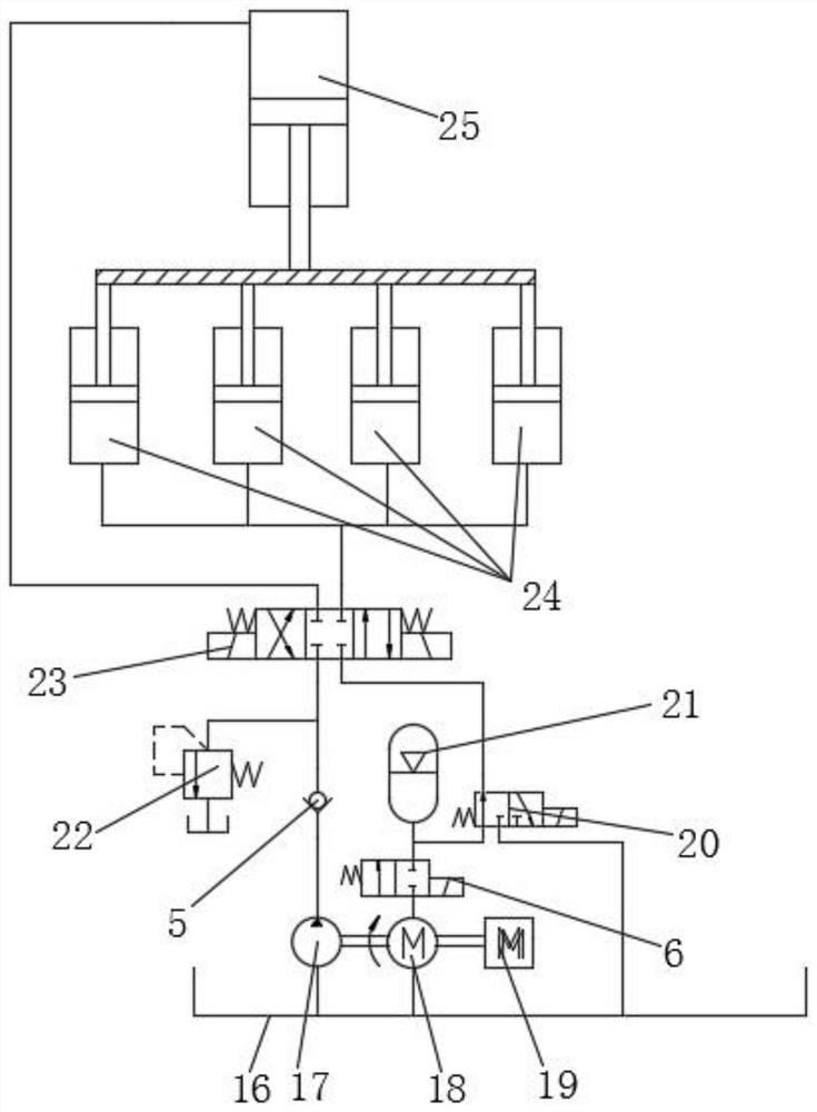
[0036] Example 1, such as image 3 As shown, take a certain pressure as an example;

[0037] (1), the original use of 45KW servo drive, 50KW servo motor, 80cc+80cc double variable speed hydraulic pump.

[0038] (2) The main oil cylinder is a single-acting oil cylinder with a bore of 510mm, a stroke of 1600mm, and a maximum working pressure of 25Mpa.

[0039] (3) Ascending auxiliary cylinder single-acting oil cylinder, bore 120mm, stroke 1600mm, 4 cylinders connected in parallel.

[0040] (4) The self-weight descending accumulator of the main oil cylinder can recover hydraulic energy above 72L / min.7Mpa from the ascending auxiliary cylinder.

[0041] (5) The power assist mechanism is designed with a displacement of 200CC, and the accumulator recovers 72L / min.7Mpa hydraulic energy, which can provide an output torque of 200N / m, and can provide torque assist for 9 seconds at a maximum volumetric efficiency of 80% at 2000 rpm.

[0042] (6), the above conditions show that increasi...

Embodiment 2

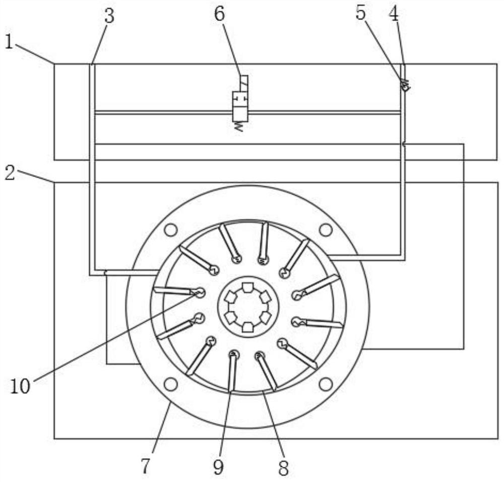
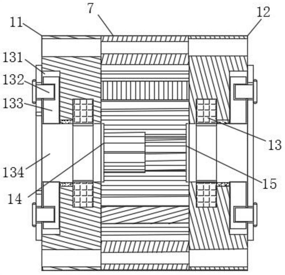
[0043] Example 2, such as Figure 4-5 As shown, when the variable speed hydraulic pump 17 and the servo motor 19 are disassembled, the spline bushing 134 can drive the four sets of positioning plates 133 into the arc groove 131 in advance, and the movement of the spline bushing 134 can be used to drive The rotating oil seal 13 seals the interior of the stator 7, and then the splined bushing 134 drives the positioning plate 133 to move in the arc-shaped groove 131, so that the positioning plate 133 moves to a designated position, and the positioning plate 133 is fixed by the fixing pin 132, And then the output shaft of the variable speed hydraulic pump 17 and the servo motor 19 is installed, and the sealing effect in the stator 7 is increased to prevent the oil from leaking when the motor is in operation.

[0044] Working principle: when the press is descending, the self-weight potential energy generated by the descending of the press is recovered and stored through the accumul...


PUM


Abstract

The invention discloses a hydraulic device for feeding back output torque of a power assisting servo motor by utilizing self-weight potential energy. The hydraulic device comprises an oil tank, a variable-speed hydraulic pump, a power assisting mechanism, the servo motor and an energy accumulator. The power assisting mechanism is connected with the variable-speed hydraulic pump and the servo motor, the power assisting mechanism is led to a high-pressure oil port and a low-pressure oil return port, a second electromagnetic directional valve is arranged in an oil cavity of the low-pressure oil return port, and four sets of rising auxiliary cylinders and a main oil cylinder are arranged above the second electromagnetic directional valve. According to the hydraulic device for feeding back output torque of the power assisting servo motor by utilizing self-weight potential energy, a rotor is pushed by hydraulic pressure to drive the servo motor shaft and a variable-speed hydraulic pump shaft, so that the servo motor achieves high-torque transmission with less output torque to drive the variable-speed hydraulic pump, the low-power servo motor can provide high-power output in a short time, the starting speed is higher, output and adjustment control are more stable and accurate, the energy-saving effect is achieved, a coupler is replaced, and the structural size and the power cost of a power source are reduced.

Description

technical field [0001] The invention relates to the technical field of servo motors, in particular to a hydraulic device that utilizes self-weight potential energy feedback to assist servo motors to output torque. Background technique [0002] The servo motor can control the speed and position accuracy very accurately. It can convert the voltage signal into torque and speed to drive the control object. The rotor speed of the servo motor is controlled by the input signal and can respond quickly. In the automatic control system, it is used as an execution It has the characteristics of small electromechanical time constant and high linearity, and can convert the received electrical signal into angular displacement or angular velocity output on the motor shaft. [0003] When the servo motor is used, the output power and control requirements are relatively large. When controlling the maximum speed of the motor, the friction in the motor rotation group produces resistance, resulti...

Claims


Application Information

Patent Timeline
Patent Type & Authority Applications(China)
IPC IPC(8): F15B1/02F15B11/16F15B13/06F15B21/14F16J15/16
CPCF15B1/02F15B11/16F15B13/06F15B21/14F16J15/16
Inventor 朱耀义谭海凡王学国周文丰杨洋陈亮徐彦
Owner 深圳市科斯腾液压设备有限公司
Learn More