High-definition optical lens ultrasonic cleaning method

An optical lens and ultrasonic technology, applied in the field of optical lenses, can solve problems such as lens surface scratches, lens damage, and reduction of optical lens cleaning efficiency.

Inactive Publication Date: 2021-07-30
湖北省优迈科技有限公司
View PDF0 Cites 3 Cited by
  • Summary
  • Abstract
  • Description
  • Claims
  • Application Information

AI Technical Summary

Problems solved by technology

[0003] The current optical lenses will produce dust, oil stains, sweat stains, fingerprints and other dirt during the polishing process. The polished optical lenses need to be cleaned by an ultrasonic cleaning machine. The following problems exist in the process of ultrasonic cleaning of optical lenses today: The clamping device of the lens cannot be adjusted according to the model size of the optical lens, and it is easy to scratch the surface of the lens when clamping the optical lens, resulting in damage to the lens; the optical lens cannot be turned over during the cleaning process, resulting in insufficient cleaning , which reduces the ultrasonic cleaning effect; the traditional cleaning operation is to place the lens in the cleaning machine for cleaning, then take out the cleaned lens, and then transfer it to the drying equipment. This cleaning process is cumbersome and increases the cleaning process. , thereby reducing the cleaning efficiency of optical lenses; for this reason, the present invention provides an ultrasonic cleaning method for high-definition optical lenses

Method used


Image

  • High-definition optical lens ultrasonic cleaning method
  • High-definition optical lens ultrasonic cleaning method
  • High-definition optical lens ultrasonic cleaning method

Examples


Embodiment Construction

[0034]In order to make the technical means, creative features, goals and effects achieved by the present invention easy to understand, the present invention will be further elaborated below in conjunction with specific drawings. It should be noted that, in the case of no conflict, the embodiments and Features in the embodiments can be combined with each other.

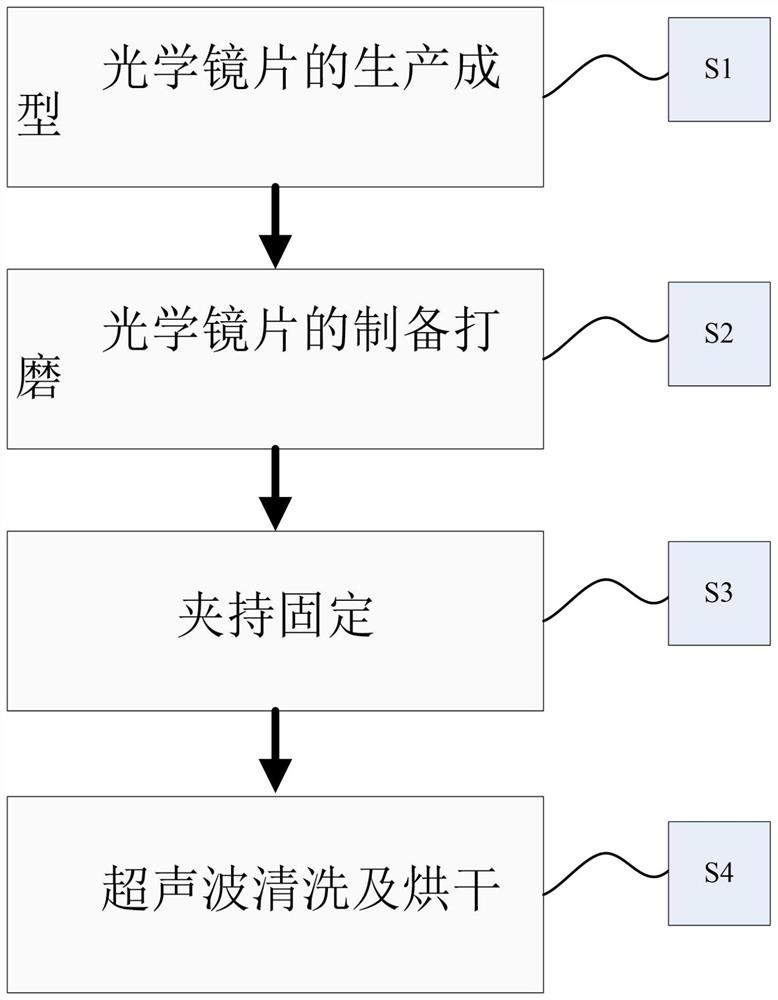
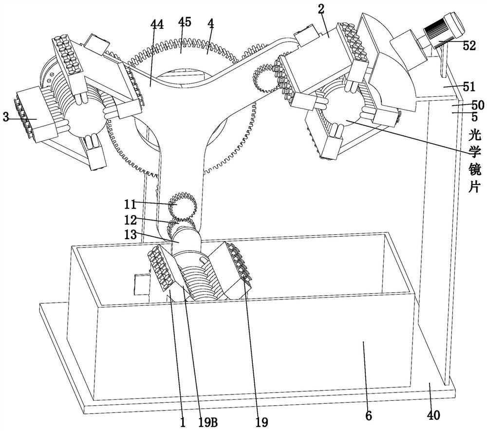
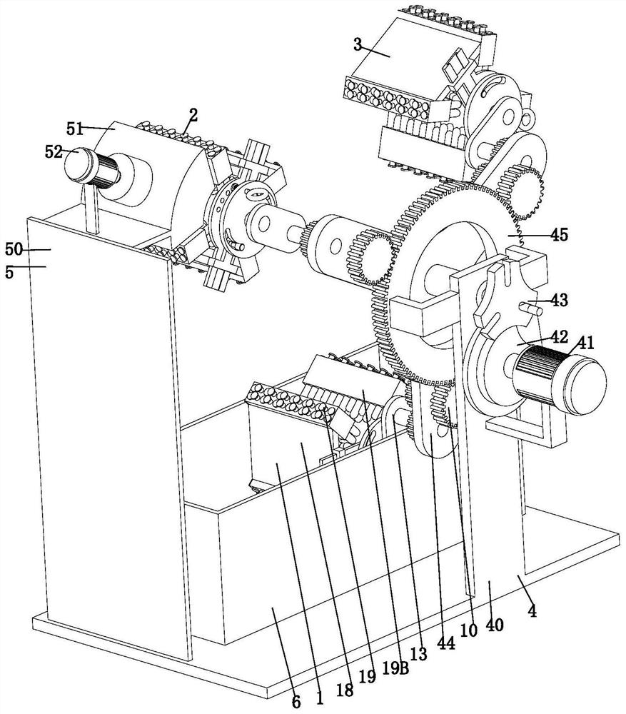
[0035] like Figure 1 to Figure 10 As shown, a high-definition optical lens ultrasonic cleaning method, which uses a high-definition optical lens ultrasonic cleaning equipment, the cleaning equipment includes a rotary clamping mechanism 1, a rotary clamping mechanism 2, a rotary clamping mechanism 3 3. The driving mechanism 4, the drying mechanism 5 and the cleaning tank 6, the specific method of ultrasonically cleaning the optical lens by using the above cleaning equipment is as follows:

[0036] S1. Production and molding of optical lenses: the raw materials are mixed with oxides of high-purity silicon, boron, sodiu...


PUM


Abstract

The invention provides a high-definition optical lens ultrasonic cleaning method. A first rotary clamping mechanism, a second rotary clamping mechanism, a third rotary clamping mechanism, a driving mechanism, a drying mechanism and a cleaning tank are included. The high-definition optical lens ultrasonic cleaning method solves the following problems existing in the existing ultrasonic cleaning process of the optical lens, wherein the problems include the problem that a clamping device of the optical lens cannot be adjusted according to the model and size of the optical lens, and when the optical lens is clamped, the surface of the lens is likely to be scratched to cause damage to the lens, the problem that due to the fact that the optical lens cannot be overturned in the cleaning process, the cleaning is not thorough, and the ultrasonic cleaning effect is reduced, and the problem that due to the fact that during traditional cleaning operation, the lens is placed in a cleaning machine to be cleaned, then the cleaned lens is taken out and then transferred into drying equipment, the cleaning process is tedious, the cleaning process is increased, and then the cleaning efficiency of the optical lens is reduced.

Description

technical field [0001] The invention relates to the technical field of optical lenses, in particular to an ultrasonic cleaning method for high-definition optical lenses. Background technique [0002] Optical glass lenses are mixed with high-purity silicon, boron, sodium, potassium, zinc, lead, magnesium, calcium, barium and other oxides according to a specific formula, melted at high temperature in a platinum crucible, stirred evenly with ultrasonic waves, and removed air bubbles; Slowly cool down for a long time to avoid internal stress in the glass block; the cooled glass block is heated and forged to form an optical lens blank, and then polished to form an optical lens; [0003] The current optical lenses will produce dust, oil stains, sweat stains, fingerprints and other dirt during the polishing process. The polished optical lenses need to be cleaned by an ultrasonic cleaning machine. The following problems exist in the process of ultrasonic cleaning of optical lenses t...

Claims


Application Information

Patent Timeline
Patent Type & Authority Applications(China)
IPC IPC(8): B08B3/12B08B11/02B08B13/00F26B21/00
CPCB08B3/123B08B11/02B08B13/00F26B21/001
Inventor 王自林
Owner 湖北省优迈科技有限公司
Why Eureka
Try Eureka