Eureka AIR delivers breakthrough ideas for toughest innovation challenges, trusted by R&D personnel around the world.

Full-automatic selective wave soldering device

A wave soldering and selective technology, applied in the direction of tin feeding device, auxiliary device, welding equipment, etc., can solve the problems of complicated installation, high mechanical loss, and bulky

Pending Publication Date: 2021-07-30
埃斯特(深圳)智能科技有限公司
View PDF9 Cites 0 Cited by
  • Summary
  • Abstract
  • Description
  • Claims
  • Application Information

AI Technical Summary

Problems solved by technology

[0004] 1. The flux spraying mechanism has disadvantages such as large structure and heavy weight, and the cost is high;
[0005] 2. The existing upper preheating module uses the motor, volute and turbine to drive the air, which has the problems of complex structure, inconvenient maintenance and high mechanical loss;
[0006] 3. The dual-axis width-adjusting components used on the existing transport guide rails have a large span, are easily deformed, have a bulky structure, and are complicated to install;
The four screw rods are realized by the synchronous belt, the synchronous belt deforms and jumps teeth, it is difficult to ensure that the screw rods are completely synchronized, so they often get stuck;
[0008] 5. The display components in the existing equipment are placed at the exit of the equipment, which will affect the docking of downstream equipment

Method used


Image

  • Full-automatic selective wave soldering device
  • Full-automatic selective wave soldering device
  • Full-automatic selective wave soldering device

Examples


Embodiment

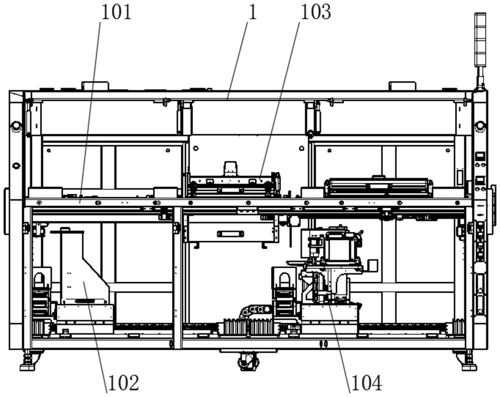
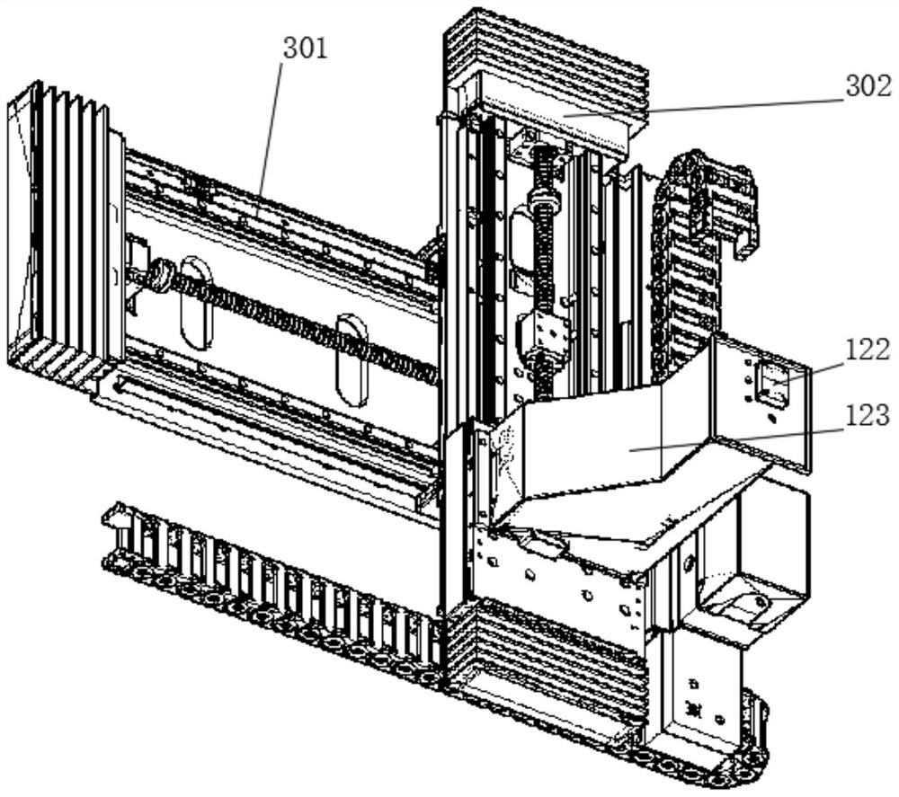
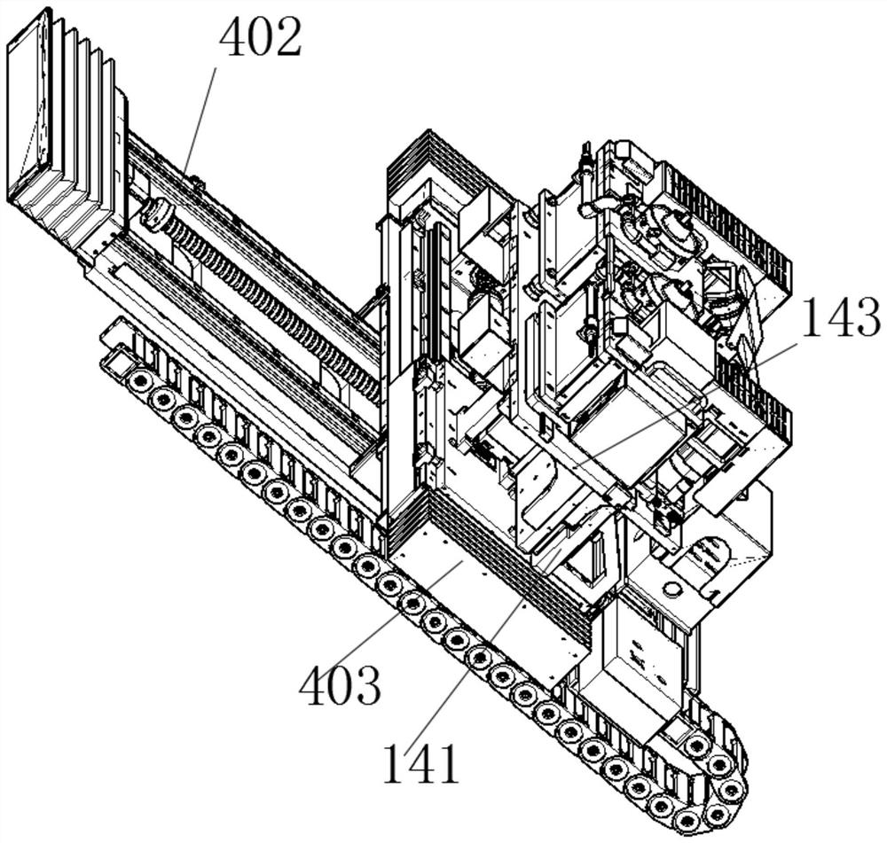
[0037] see Figure 1 to Figure 10 , the present invention provides a technical solution: a fully automatic selective wave soldering device, including a main body 1 and a transport rail 101 arranged inside the main body 1, a flux spraying mechanism 102, a double-layer preheating mechanism 103 and a selective soldering mechanism 104. The transportation guide rail 101 includes a board-in guide rail and a board-out guide rail. Multiple single-axis width adjustment components 9 are arranged on the board-in guide rail. The precision spray valve 122, the driven guide rail 302 is set on the active guide rail 301, the movable platen 123 is installed on the driven guide rail 302, and the high-precision spray valve 122 is set on the top of the movable platen 123, the double-layer preheating mechanism 103 includes The upper preheating module and the lower preheating module, the upper preheating module includes the shell 8, the heat pipe 6 and the rectifying copper pipe 7, the selective we...


PUM


Abstract

The invention discloses a full-automatic selective wave soldering device. The device comprises a main body, a conveying guide rail, a scaling powder spraying mechanism, a double-layer preheating mechanism and a selective soldering mechanism, wherein the conveying guide rail, the scaling powder spraying mechanism, the double-layer preheating mechanism and the selective soldering mechanism are arranged on the inner side of the main body, the conveying guide rail comprises a plate feeding guide rail and a plate discharging guide rail, and a plurality of single-shaft width adjusting assemblies are arranged on the plate feeding guide rail; the scaling powder spraying mechanism comprises a driving guide rail, a driven guide rail, a movable platen and a high-precision spraying valve, the driven guide rail is arranged on the driving guide rail, and the movable platen is mounted on the driven guide rail; and the high-precision spraying valve in the scaling powder spraying mechanism is reduced by a half, the cost is reduced by nearly a half under the condition of not affecting the efficiency, the structure is obviously reduced, and the device is portable and flexible. According to the device, an upper preheating module passes through a rectifying copper pipe with rectifying fine holes and is heated by a heating pipe to directly form hot airflow to directly heat a product; and the device is simple and small in structure, convenient to maintain, free of mechanical rotation and low in mechanical loss.

Description

technical field [0001] The invention belongs to the technical field of welding equipment, and in particular relates to a fully automatic selective wave soldering device. Background technique [0002] Fully automatic selective wave soldering, also known as selective soldering, is a device in the field of PCB plug-in through-hole soldering. It is a multi-axis manipulation platform controlled by a program and equipped with a flux nozzle and a tin furnace. In the field of PCB through-hole welding in recent years, it has gradually become a popular trend of through-hole welding, which is applied to multi-layer PCB through-hole welding with high welding requirements and complicated processes. It has the advantages of high production efficiency and large output in the manufacture of through-hole component circuit boards, so it used to be the most important welding equipment in the automated mass production of electronic products. [0003] The existing fully automatic selective wave...

Claims


Application Information

Patent Timeline
IPC IPC(8): B23K3/06B23K3/08H05K3/34B23K101/42
CPCB23K3/0638B23K3/08B23K3/082B23K3/087H05K3/34
Inventor 耿丽文
Owner 埃斯特(深圳)智能科技有限公司
Why Eureka
Eureka Blog
Learn More