Thick material cutting method for dynamically controlling three-dimensional track of laser spot and system of method

A cutting method and three-dimensional trajectory technology, applied in laser welding equipment, manufacturing tools, welding equipment, etc., can solve the problems of difficulty in meeting actual processing and production needs, low economic applicability, and low production efficiency.

Active Publication Date: 2021-07-30
FOSHAN HONGSHI LASER TECH CO LTD
View PDF9 Cites 6 Cited by
  • Summary
  • Abstract
  • Description
  • Claims
  • Application Information

AI Technical Summary

Problems solved by technology

[0003] However, in the field of laser thick material processing, due to the influence of laser processing power, laser spot energy distribution and laser beam quality, in the actual production process of laser processing of thick material workpieces, the thick material processing section is prone to defects such as stripes and dross , which greatly affects the surface processing quality of thick material workpieces; and in the traditional laser cutting process, the static spot of the laser will lead to the phenomenon of hyperbolic cross-section before and after the focus of the laser optical path transmission direction, which makes the post-processing of laser processing heavy. Low efficiency and poor economic benefits
In the field of laser thick material processing, the section quality of the processed surface of thick material workpieces has always been the core issue of laser processing. In the prior art, the method of optimizing the laser spot energy shaping optical system is generally used to improve the section quality of thick material workpieces, but this The economic applicability of the method is low, and it is difficult to meet the complex and changeable actual processing and production needs

Method used


Image

  • Thick material cutting method for dynamically controlling three-dimensional track of laser spot and system of method
  • Thick material cutting method for dynamically controlling three-dimensional track of laser spot and system of method
  • Thick material cutting method for dynamically controlling three-dimensional track of laser spot and system of method

Examples


Embodiment 1

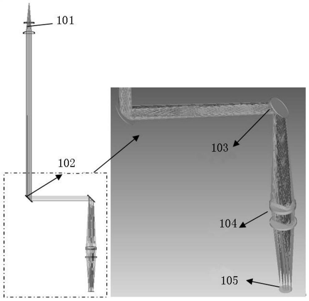
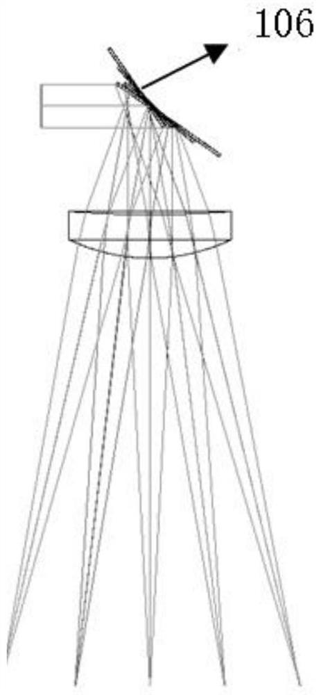
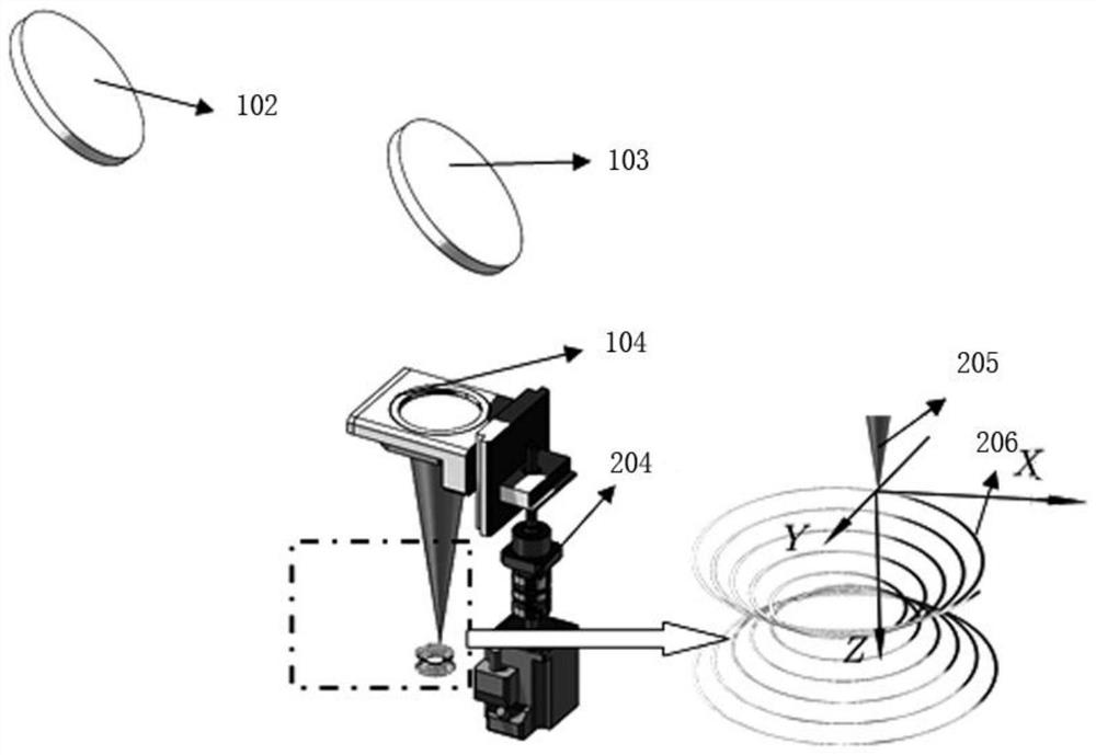
[0057] Such as Figure 1-Figure 3 As shown, a thick material cutting method with dynamic control of the three-dimensional trajectory of the laser spot includes a laser that emits laser light, uses a collimator lens 101 to collimate and distribute the laser beam, and uses a mirror 102 and a vibrating mirror assembly 103 to change the collimation. The optical path of the laser beam uses the focusing lens assembly 104 to focus the collimated laser beam, and the focused laser is shot onto the thick material 105 to be cut, and the focal spot of the laser is controlled to fall in the thick material 105 to be cut, along the predetermined The cutting track moves the focal spot of laser cutting to complete the cutting of thick materials;

[0058]During the cutting process, the focus spot is controlled to perform high-frequency vibration on the cutting track. Among them, the high-frequency vibration with a high-frequency frequency of 20kHz and an amplitude of 20-50μm can optimize the CO...

Embodiment 2

[0094] One of the embodiments of the present invention, the main technical solution of this embodiment is basically the same as that of Embodiment 1, and the features not explained in this embodiment are explained in Embodiment 1, and will not be repeated here. The difference between this embodiment and embodiment 1 is:

[0095] In the thick material cutting method, during the cutting process, the focal spot is controlled to perform high-frequency vibration on the cutting track, and the high-frequency frequency is 2.1kHz-3kHz.

Embodiment 3

[0097] One of the embodiments of the present invention, the main technical solution of this embodiment is basically the same as that of Embodiment 1, and the features not explained in this embodiment are explained in Embodiment 1, and will not be repeated here. The difference between this embodiment and embodiment 1 is:

[0098] In the thick material cutting method, during the cutting process, the focal spot is controlled to perform high-frequency vibration on the cutting track, and the high-frequency frequency is 3.1kHz-4kHz.


PUM


Abstract

The invention discloses a thick material cutting method for dynamically controlling a three-dimensional track of a laser spot and a system of the method, and belongs to the field of laser processing. The system comprises a laser device for emitting lasers. A collimating lens is used for collimating and distributing laser beams, a reflector is used for changing the light path of the collimated laser beams, a focusing lens assembly is used for focusing the collimated laser beams, the focused lasers are emitted to a to-be-cut thick material, a focus light spot of the lasers is controlled to fall into the to-be-cut thick material, the focus light spot of laser cutting is moved along a preset cutting track, and cutting of the thick material is completed; in the cutting process, the focus light spot is controlled to conduct high-frequency vibration on the cutting track, and the high frequency ranges from 1.5 kHz to 4 kHz; and through dynamic control over the three-dimensional track of the laser spot, high-frequency movement of the spot focus in all directions of the optical axis is achieved, and therefore energy distribution of a section heat affected zone of a thick material workpiece is adjusted, the phenomena of slag adhering, thick stripes and the like generated by laser cutting of the section are avoided, and the section processing quality is improved.

Description

technical field [0001] The invention belongs to the field of laser processing, and in particular relates to a method and system for cutting thick materials with dynamic control of three-dimensional trajectory of laser spot. Background technique [0002] Laser processing is a processing method in which the workpiece is placed under a focused beam of high energy density, and the surface of the workpiece is eroded by using the photothermal effect. With the development of laser processing technology, because the focused beam has the advantages of high energy density and high concentration during laser processing, laser processing is becoming more and more important in the field of material processing. [0003] However, in the field of laser thick material processing, due to the influence of laser processing power, laser spot energy distribution and laser beam quality, in the actual production process of laser processing of thick material workpieces, the thick material processing...

Claims


Application Information

Patent Timeline
Patent Type & Authority Applications(China)
IPC IPC(8): B23K26/064B23K26/082B23K26/38
CPCB23K26/064B23K26/0643B23K26/0648B23K26/082B23K26/38
Inventor 杜斌常勇
Owner FOSHAN HONGSHI LASER TECH CO LTD
Why Eureka
Try Eureka