Shot blasting machine for rust removal of steel member

A technology of steel components and shot blasting machines, which is applied in the direction of abrasive jetting machine tools, used abrasive processing devices, explosion generating devices, etc., which can solve the problems of increased labor intensity and operational safety risks, inability to remove, cleaning equipment selection and arrangement Unreasonable and other issues

Inactive Publication Date: 2021-07-30
TONGLING FERROUS CONSTR & INSTALLATION STEEL STRUCTURE
View PDF0 Cites 1 Cited by
  • Summary
  • Abstract
  • Description
  • Claims
  • Application Information

AI Technical Summary

Problems solved by technology

[0003] In the existing shot blasting machine, the design length of the cleaning room is relatively short, and the selection and layout of the cleaning equipment are unreasonable. Increased labor intensity and operational safety risks

Method used


Image

  • Shot blasting machine for rust removal of steel member
  • Shot blasting machine for rust removal of steel member
  • Shot blasting machine for rust removal of steel member

Examples


Embodiment

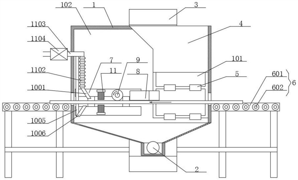
[0033] Such as figure 1 As shown, the shot blasting machine for derusting steel components includes a casing 1 and a hoist 3. A support mechanism 6 for supporting steel plates is provided outside the casing 1. A lower screw conveyor 2 is connected through the lower end of the casing 1. The interior of the shell 1 is provided with a shot blasting chamber 101 and a cleaning chamber 102. The interior of the shot blasting chamber 101 is provided with a pellet ash separator 4, and a shot blasting device 5 is provided below the pellet ash separator 4. The shot conveying mechanism is connected with the shot blasting device 5, the upper end of the hoist 3 is located above the shot ash separator 4, and the lower end of the hoist 3 is located below the lower screw conveyor 2;

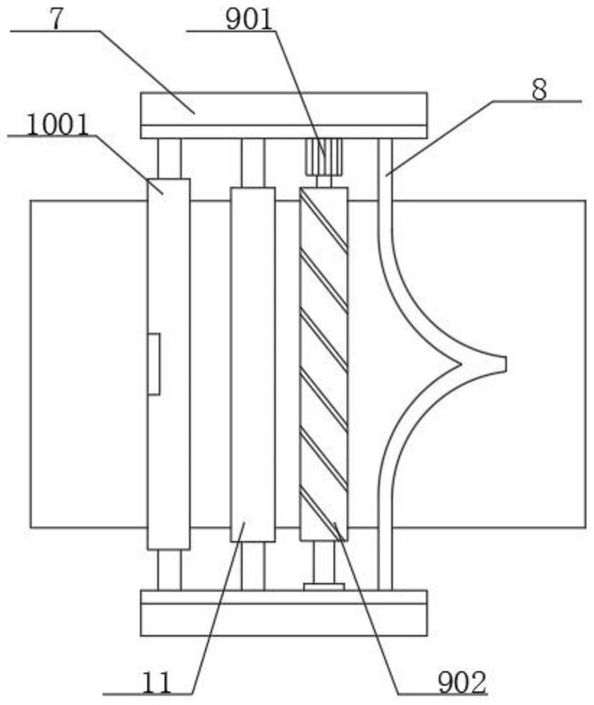
[0034] The inner wall of the cleaning chamber 102 is connected with a receiving mechanism 7, and the receiving mechanism 7 is connected with a scraper 8, a rolling brush cleaning mechanism 9, a secondary cleaning...


PUM


Abstract

The invention relates to the technical field of shot blasting machines, in particular to a shot blasting machine for rust removal of a steel member. A supporting mechanism for supporting a steel plate is arranged on the outer portion of a machine shell, the lower end of the machine shell is connected with a lower spiral conveyor in a penetrating manner, a shot blasting chamber and a cleaning chamber are arranged in the machine shell, a shot-ash separator is arranged in the shot blasting chamber, a shot blasting device is arranged below the shot-ash separator, and the shot-ash separator is connected with the shot blasting device through a steel shot conveying mechanism. A scraping plate scrapes off most of steel shots on the surface of the steel member, a rolling brush cleaning mechanism cleans away the steel shots remaining on the surface of the steel member, a secondary cleaning mechanism cleans away dust on the surface of the steel member, and a high-pressure dust blowing mechanism blows off the dust on the surface of the steel member. By means of the shot blasting machine for rust removal of the steel member, the problem that after shot blasting, a large number of steel shots remain on the steel member is solved, shots and dust remaining on the surface of the steel member are thoroughly removed, and labor intensity and operation safety risks are reduced.

Description

technical field [0001] The invention relates to the technical field of shot blasting machines, in particular to a shot blasting machine for derusting steel components. Background technique [0002] Shot blasting machine is also called sand blasting machine or sandblasting machine. Shot blasting machine is a processing technology that impacts steel sand and steel shots on the surface of material objects through high-speed shot blasting. It is faster and more efficient than other surface treatment techniques and can be used for part retention or post-stamping casting processes. [0003] In the existing shot blasting machine, the design length of the cleaning room is relatively short, and the selection and layout of the cleaning equipment are unreasonable. Increased labor intensity and job safety risks. Contents of the invention [0004] Aiming at the deficiencies of the prior art, the invention provides a shot blasting machine for derusting steel components. [0005] The ...

Claims


Application Information

Patent Timeline
Patent Type & Authority Applications(China)
IPC IPC(8): B24C1/08B24C3/00B24C5/06B24C9/00
CPCB24C1/086B24C3/00B24C5/06B24C9/006
Inventor 姚胜红俞家胜秦珍
Owner TONGLING FERROUS CONSTR & INSTALLATION STEEL STRUCTURE
Why Eureka
Try Eureka