
Cooling treatment device used for acid fracturing truck

A processing device, acid fracturing technology, applied in household refrigeration devices, fluid pressure actuation devices, engine cooling, etc., can solve the problems of inability to alternately change the position of fin plates, inconvenient use, slow cooling speed, etc.

Inactive Publication Date: 2021-07-30
HUBEI PETROKH MACHINE MFG
View PDF0 Cites 0 Cited by
  • Summary
  • Abstract
  • Description
  • Claims
  • Application Information

AI Technical Summary

Problems solved by technology

[0002] Acid fracturing operation refers to that the externally mixed acid liquid is pressurized by the horizontal plunger pump set on the fracturing platform, and injected into the bottom of the well at a pressure higher than the fracture pressure of the ground, and the formation is crushed to form artificial fractures and utilized Acid corrodes cracks and improves the crude oil penetration capacity of the formation. The cooling device of the fracturing truck is an important part of the fracturing truck, which is directly related to the use efficiency of the whole fracturing truck. The existing cooling treatment device uses a hydraulic motor to drive the fan for cooling. The system is used to cool the engine cylinder jacket water, intercooler water, transmission case oil, power end lubricating oil and hydraulic oil on the fracturing vehicle. The existing cooling device cannot alternately change the position of the fin plate during use, so that It is impossible to quickly absorb the heat inside the pipeline. In addition, the existing cooling device can only cool down through a single air cooling method, which is inconvenient to use and slow in cooling speed

Method used


Image

  • Cooling treatment device used for acid fracturing truck
  • Cooling treatment device used for acid fracturing truck
  • Cooling treatment device used for acid fracturing truck

Examples


Embodiment approach

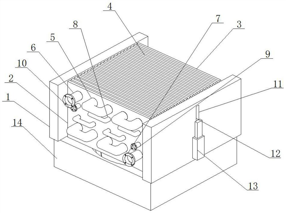
[0027] As a preferred embodiment of the present invention, the installation frame 17 is provided with an installation cavity 19, and a DC motor 20 is fixed inside the installation cavity 19, and a fan blade 21 is installed on the DC motor 20. The leaves 21 cooperate with the finned plate 4 .

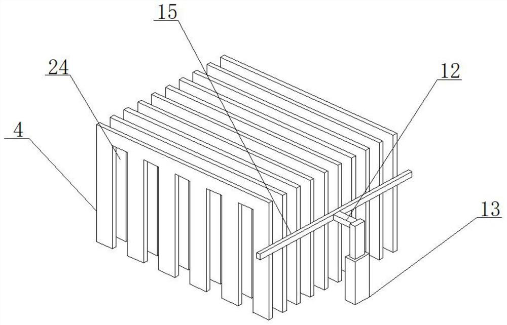
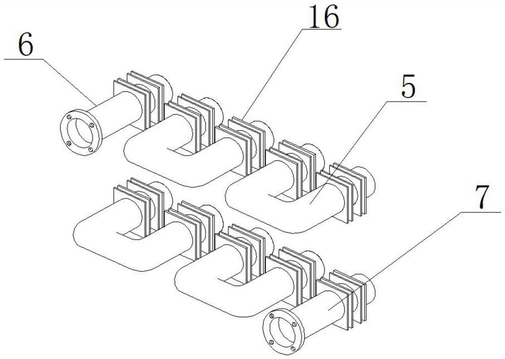
[0028] As a preferred embodiment of the present invention, a fixing ring is welded on the pipeline 5, a splint 16 is welded on the fixing ring, a fixing groove 24 is opened on the fin plate 4, and the fin plate 4 passes through The fixing groove 24 is installed between the clamping plates 16 .

[0029] As a preferred embodiment of the present invention, a metal plate 22 is welded on the cooling pipe 8 , the metal plate 22 is made of a heat-absorbing material, and one end of the metal plate 22 is matched with the pipe 5 .

[0030] As a preferred embodiment of the present invention, a fin plate 23 is installed between the fin plates 4, and a fixing groove 1 is opened on the fin plate 23, ...


PUM


Abstract

The invention provides a cooling treatment device used for an acid fracturing truck. The cooling treatment device comprises a cooling treatment device body, the cooling treatment device body comprises a supporting plate, a mounting plate and a fixing plate are welded on the supporting plate, fin plates are mounted between the mounting plate and the fixing plate, pipelines are mounted on the mounting plate and the fixing plate, a liquid outlet pipe and a liquid inlet pipe are mounted at the two ends of the pipelines correspondingly, cooling pipes are mounted at the bottoms of the pipelines, and a water inlet and a water drain opening are mounted at the two ends of the cooling pipes correspondingly. When the cooling treatment device used for the acid fracturing truck is used, the fin plates are pushed to move up and down through an electric push rod, and therefore after heat in the pipelines is adsorbed for a certain time, the fin plates at the high-temperature position are separated from clamping plates, the cooled fin plates move up and down to make contact with the clamping plates to absorb heat again, heat absorption changes are conducted through cold and heat alternation, and therefore the heat in the pipelines is rapidly removed.

Description

technical field [0001] The invention relates to the field of cooling treatment equipment for fracturing vehicles, in particular to a cooling treatment device for acidifying fracturing vehicles. Background technique [0002] Acid fracturing operation refers to that the externally mixed acid liquid is pressurized by the horizontal plunger pump set on the fracturing platform, and injected into the bottom of the well at a pressure higher than the fracture pressure of the ground, and the formation is crushed to form artificial fractures and utilized Acid corrodes cracks and improves the crude oil penetration capacity of the formation. The cooling device of the fracturing truck is an important part of the fracturing truck, which is directly related to the use efficiency of the whole fracturing truck. The existing cooling treatment device uses a hydraulic motor to drive the fan for cooling. The system is used to cool the engine cylinder jacket water, intercooler water, transmission...

Claims


Application Information

Patent Timeline
Patent Type & Authority Applications(China)
IPC IPC(8): F01P11/00F01P5/02F02B29/04F16H57/04F15B21/0423F25D31/00F28F13/12
CPCF01P5/02F01P11/00F02B29/0431F02B29/0456F16H57/0413F16H57/0415F16H57/0416F25D31/00F28F13/12F15B21/0423Y02T10/12
Inventor 梁峰胡健
Owner HUBEI PETROKH MACHINE MFG
Learn More