Eureka AIR delivers breakthrough ideas for toughest innovation challenges, trusted by R&D personnel around the world.

Motor moving device for cooperating with hydraulic motor test bench and control method thereof

A technology of hydraulic motor and mobile device, which is applied to fluid pressure actuating devices, optical devices, measuring devices, etc., can solve the problems of low safety, increased staff burden, and difficult adjustment, and achieves improved automation and intelligence. , The effect of reducing complex operation steps and reducing labor intensity

Active Publication Date: 2022-06-21
JIANGSU MASADA HEAVY INDS
View PDF7 Cites 0 Cited by
  • Summary
  • Abstract
  • Description
  • Claims
  • Application Information

AI Technical Summary

Problems solved by technology

[0004] At present, there are the following problems in the assembly process of the hydraulic motor and the coupling: (1) Before the test, the hydraulic motor needs to be moved by manual handling or hoisting, etc., and the operation steps are complicated, which increases the burden on the staff; (2) The motor needs to be transported repeatedly, and the motor may also collide during the transport process; (3) Since the stop angle of the coupling is unknown, during assembly, it is necessary to manually adjust the assembly angle of the hydraulic motor according to the angle of the coupling, which is difficult to adjust , and increase the work intensity of the workers. In addition, during the angle adjustment process, the hydraulic motor may collide with the test bench and cause damage, which is less safe.
[0005] At present, the existing motor moving device solves the above problems. The motor automatic conveying mechanism described in the patent ZL201521007580.3 is expected to realize the automatic conveying of the DC motor by setting related mechanisms and sensors. However, due to the huge difference in the structure of the electric motor and the hydraulic motor , does not solve the above problems

Method used


Image

  • Motor moving device for cooperating with hydraulic motor test bench and control method thereof
  • Motor moving device for cooperating with hydraulic motor test bench and control method thereof
  • Motor moving device for cooperating with hydraulic motor test bench and control method thereof

Examples


Embodiment Construction

[0101] Specific embodiments of the present invention will be described in detail below with reference to the accompanying drawings.

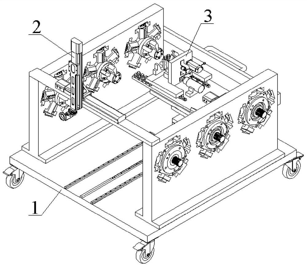
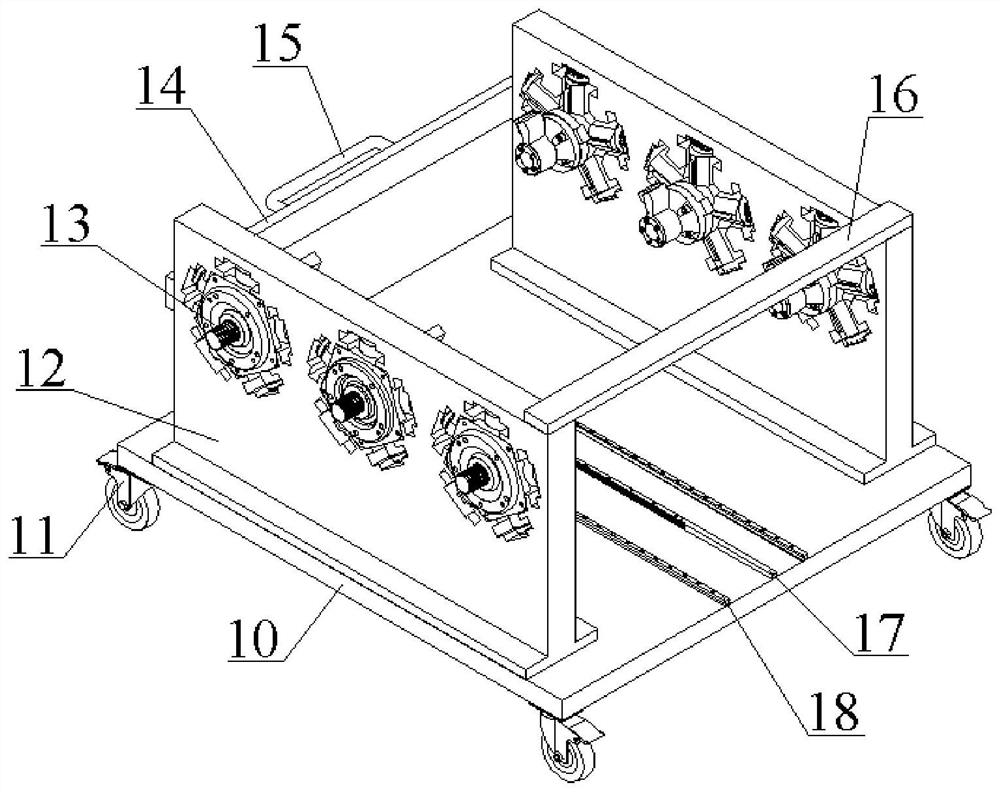
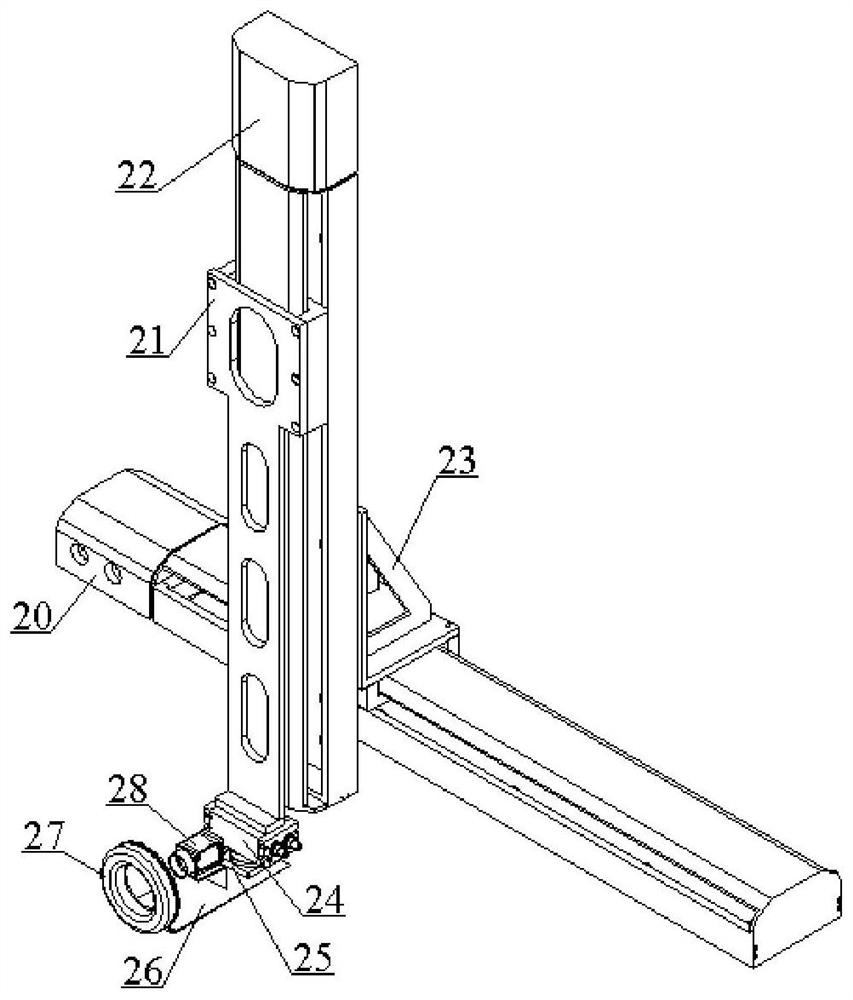
[0102] like Figure 1-3 As shown in FIG. 5 , a motor moving device for matching with a hydraulic motor test bench includes a motor storage device 1 , a visual inspection system 2 and a material moving device 3 . The horizontal linear module 20 of the visual inspection system 2 is arranged on the visual inspection system mounting plate 16 of the motor storage device 1. The first pinion 3003 of the moving device 3 meshes with the rack 17 of the motor storage device 1, and passes through the first pinion 3003 of the motor storage device 1. The sliding block 3000 is installed on the motor storage device 1 in cooperation with the first guide rail 18 , and can move along the first guide rail 18 at the same time.

[0103] like figure 2 As shown, the motor storage device 1 includes a storage rack mounting plate 10 , rollers 11 , and a motor storage r...


PUM


Abstract

The invention discloses a motor moving device for cooperating with a hydraulic motor test bench, which includes a motor storage device, a device for taking pictures of the output shaft end of the hydraulic motor to be inspected and the shaft coupling end of the motor test bench to detect their matching angles The visual inspection system and the material transfer device transport the hydraulic motor to be inspected at the motor storage device to the visual inspection system; the visual inspection system and the material transfer device are driven by the computer control center. The invention also discloses a control method for the motor moving device matched with the hydraulic motor test bench.

Description

technical field [0001] The invention relates to the technical field of hydraulic motor testing equipment, in particular to a motor moving device used for matching with a hydraulic motor testing bench. Background technique [0002] The interior of the hydraulic motor adopts a static pressure balance design, which has the following characteristics: (1) It has a five-plunger structure with a lower excitation frequency of the eccentric shaft, so its noise is low; (2) The starting torque is large, the low-speed stability is good, and the energy It runs smoothly at a very low speed; (3) the rotation direction is reversible, and the output shaft is allowed to bear a certain radial external force; (4) it has a high power-to-mass ratio, and the volume mass is relatively small. Therefore, hydraulic motors are widely used in vulcanizers, injection molding machines, marine anchor winches and various construction machinery. [0003] In order to ensure the quality of the hydraulic motor,...

Claims


Application Information

Patent Timeline
Patent Type & Authority Patents(China)
IPC IPC(8): F15B19/00G01B11/00G01B11/26G06F17/10
CPCF15B19/00G01B11/00G01B11/26G06F17/10
Inventor 贺光辉徐建傅世辉唐文献王为民黄志峰
Owner JIANGSU MASADA HEAVY INDS
Why Eureka
Eureka Blog
Learn More