Variable-cross-section disc cutter ring and design and manufacturing method thereof

A disc-shaped hob and variable cross-section technology, applied in design optimization/simulation, cutting tools, mining equipment, etc., can solve problems such as complex rock mass structure, knife ring impact, wear failure, etc., to improve rock adaptability and impact Load capacity and life-enhancing effect

Pending Publication Date: 2021-08-03
赵家立
View PDF0 Cites 0 Cited by
  • Summary
  • Abstract
  • Description
  • Claims
  • Application Information

AI Technical Summary

Problems solved by technology

This kind of disc-shaped hob cutter ring with constant cross-section often fails in the form of local wear and fracture. There are two main reasons. One is that the structure of the rock body is complex. The friction between the bodies is not enough to generate the torque to make it rotate, and the cutter ring may stop rotating for a period of time, resulting in local sliding friction, which promotes fatigue and accelerates wear failure
The second is that after the loose rock mass is broken, large rock blocks fall off, causing severe impact on the side of some knife rings, resulting in fracture failure
[0004] To sum up, the traditional disc-shaped hob has many defects in rock-breaking efficiency, service life and rock adaptability. It is necessary to propose a disc-shaped hob with higher rock-breaking efficiency and longer service life. ring, and the design and manufacture method of the knife ring that can comprehensively refer to the mechanical properties of the tunnel geological exploration surrounding rock

Method used


Image

  • Variable-cross-section disc cutter ring and design and manufacturing method thereof
  • Variable-cross-section disc cutter ring and design and manufacturing method thereof

Examples


Embodiment Construction

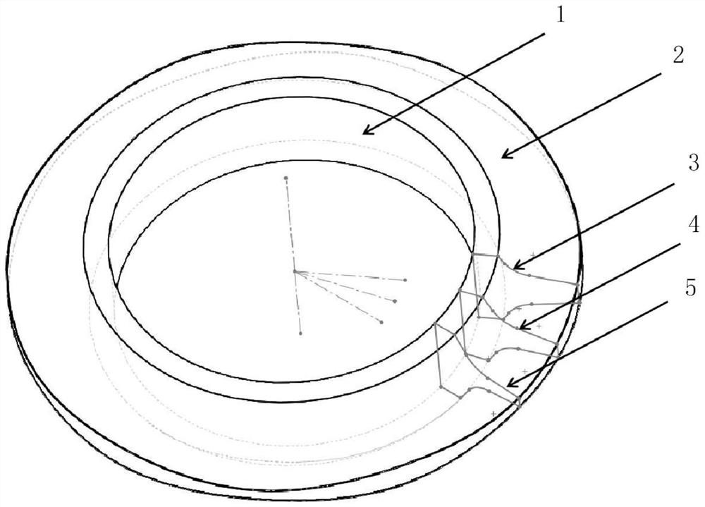
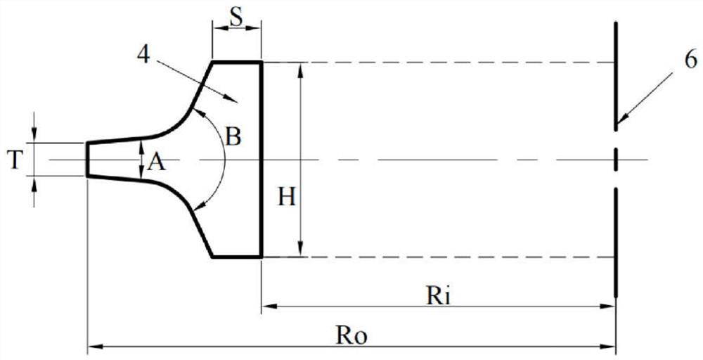
[0064] see figure 1 Shown:

[0065] A disc-shaped hob cutter ring with variable cross-section provided by the present invention includes a blade body 1 and a blade 2, the blade body 1 is a regular annular standard body of revolution, the blade 2 is arranged on the outer ring of the blade body 1, and the blade 2 is a rotary body whose radial cross-sectional profile changes regularly along the circumferential direction, and the blade width, blade angle, and blade shoulder angle change regularly along the circumferential direction.

[0066] The change of the law is that when the knife ring rotates one circle, the radial cross-sectional profile of the blade 2 experiences several complete change cycles along the circumferential direction according to a certain frequency of change, and the change rule of the radial cross-sectional profile of the blade 2 in each change cycle is the same , that is, the change range of the blade width is the same in each change period, the change rang...


PUM

PropertyMeasurementUnit
compressive strengthaaaaaaaaaa
tensile strengthaaaaaaaaaa

Abstract

The invention relates to a variable-cross-section disc cutter ring and a design and manufacturing method thereof. The variable-cross-section disc cutter ring comprises a cutter body and a blade; the cutter body is a regular annular standard rotary body; the blade is arranged on the outer ring of the cutter body; the blade is a rotary body with the radial cross section outline changing regularly in the circumferential direction; and the blade width, the blade angle and the cutter shoulder angle are regularly changed along the circumferential direction. The designing and manufacturing method comprises the steps that CAD modeling is conducted on the variable-cross-section cutter ring through parameterization design, simulation experiments and analysis are simulated based on CAE finite elements, a model of the optimal variable-cross-section cutter ring of the feature size of the variable-cross-section disc cutter ring is obtained, and blank making, punching, ring rolling and die forging technological parameter simulation of the cutter ring is conducted through CAM, and an optimal production and manufacturing process parameter scheme is obtained. The rock breaking performance of the cutter ring is improved, so that the working efficiency of the cutter ring is improved; and the failure probability of the cutter ring is reduced, and the service life of the cutter ring is prolonged.

Description

technical field [0001] The invention relates to a disc-shaped hob, in particular to a variable-section disc-shaped hob cutter ring and its design and manufacturing method. Background technique [0002] In recent years, the amount of tunnel construction has been increasing year by year, and the tunnel boring machine method has been widely promoted. The disc hob is a consumable tool for the tunnel boring machine. Performance determines the overall efficiency of tunneling work. During the tunneling process of the tunnel boring machine, under the action of the thrust and rotary torque of the tunnel boring machine, the disc hob not only revolves with the cutter head, but also rotates by itself due to the friction between it and the rock. Wedges into the rock, causing the rock to crack and crumble. The disc-shaped hob cutter ring is the core part that directly contacts, collides, squeezes and rubs with the rock mass. It improves the performance of the disc-shaped hob cutter ring...

Claims


Application Information

Patent Timeline
Patent Type & Authority Applications(China)
IPC IPC(8): E21D9/10G06F30/17G06F30/23B21D28/24B21H1/06B21J5/00B21J5/02B21K11/02
CPCB21D28/24B21H1/06B21J5/002B21J5/02B21K11/02E21D9/1006G06F30/17G06F30/23G06F2119/14
Inventor 赵家立朱先勇刘昶候振华孙靖然金百一付学伟
Owner 赵家立
Why Eureka
Try Eureka