Maximum torque current ratio control method for built-in permanent magnet synchronous motor

A permanent magnet synchronous motor, maximum torque current technology, applied in motor generator control, electronic commutation motor control, control system and other directions, can solve problems such as slow convergence speed, poor convergence performance and dynamic performance, and poor dynamic performance , to achieve the effect of improving dynamic performance, fast MTPA control, and improving startup performance

Active Publication Date: 2021-08-03
DALIAN MARITIME UNIVERSITY
View PDF5 Cites 1 Cited by
  • Summary
  • Abstract
  • Description
  • Claims
  • Application Information

AI Technical Summary

Problems solved by technology

This method has slow convergence speed, poor dynamic performance, and low torque control accuracy under the influence of torque disturbance and current / voltage harmonics
The high-frequency signal injection method processes and calculates the injected high-frequency signal and the response signal, extracts the MTPA criterion, and finally obtains the current or angle reference value, but its convergence performance and dynamic performance are poor
The virtual signal injection method superimposes a small-amplitude high-frequency sinusoidal component in the feedback current signal, and analyzes the inner relationship between the electromagnetic torque and the current vector angle by means of Taylor series expansion, and then configures a reasonable low-pass, The angle information corresponding to the MTPA control current can be extracted by using the cutoff frequency of the band-pass filter, but the use of the filter will cause a phase delay

Method used


Image

  • Maximum torque current ratio control method for built-in permanent magnet synchronous motor
  • Maximum torque current ratio control method for built-in permanent magnet synchronous motor
  • Maximum torque current ratio control method for built-in permanent magnet synchronous motor

Examples


Embodiment Construction

[0062] In order to make the technical solutions and advantages of the present invention more clear, the technical solutions in the embodiments of the present invention are clearly and completely described below in conjunction with the drawings in the embodiments of the present invention:

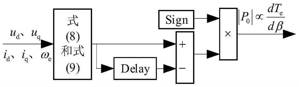
[0063] Such as figure 1 As shown, the present invention discloses a method for controlling the maximum torque-to-current ratio of a built-in permanent magnet synchronous motor, which specifically includes the following steps:

[0064] S1: According to the mathematical model of the built-in permanent magnet synchronous motor and the Lagrangian extreme value theorem, the dq axis current formula is derived;

[0065] S2: According to the further simplification of the dq-axis current relationship, redefine a variable i K , deduce dq axis current and i K The relationship between;

[0066] S3: According to the mathematical model of the built-in permanent magnet synchronous motor in the synchrono...


PUM


Abstract

The invention discloses a maximum torque current ratio control method for a built-in permanent magnet synchronous motor, and the method comprises the steps: employing a simple MTPA formula method, and achieving the real-time calculation of a dq-axis reference current based on a constant parameter model, without the need of mathematical approximation or table look-up. Besides, virtual square wave signals are injected into feedback current, MTPA criterion is extracted through difference of mechanical power before and after a square wave period, current deviation caused by parameter change is corrected, influences brought by injection of real high-frequency signals into a motor do not need to be considered, and meanwhile, dynamic performance influences brought by a filter to a system do not need to be considered. A simulation result shows that even if the change of R and Ld can cause a certain [delta] idle, the MTPA trajectory can still be tracked more accurately by combining the formula method and the virtual square wave injection method, so that the MTPA trajectory can be tracked quickly and accurately by combining the formula method and the virtual square wave injection method, and the method has stronger robustness for the parameter change of the motor.

Description

technical field [0001] The invention relates to the technical field of motor control, in particular to a method for controlling the maximum torque-to-current ratio of a built-in permanent magnet synchronous motor. Background technique [0002] The built-in permanent magnet synchronous motor has the advantages of high efficiency, high power factor, high unit power density and fast dynamic response, and has been widely used in the fields of electric propulsion ships, new energy vehicles, and household appliances. [0003] The performance characteristic of the built-in permanent magnet synchronous motor is the inductance asymmetry. Therefore, compared with the surface-mounted permanent magnet synchronous motor, the built-in permanent magnet synchronous motor not only includes the same excitation torque, but also includes reluctance torque, electromagnetic The torque is related to the d-axis current, and the reluctance torque is related to the d and q-axis currents. Using zero d...

Claims


Application Information

Patent Timeline
Patent Type & Authority Applications(China)
IPC IPC(8): H02P21/22H02P21/14
CPCH02P21/22H02P21/14
Inventor 刘彦呈郭昊昊孟兵兵张珍睿张勤进于春来
Owner DALIAN MARITIME UNIVERSITY
Why Eureka
Try Eureka