
Gas protection type refining furnace with waste heat recovery function

A waste heat recovery and gas protection technology, which is applied in the field of refining furnaces, can solve problems such as difficulty in monitoring and controlling the pressure and temperature in the furnace, the inability to quickly recover waste heat recovery technology, lack of heat preservation or enhanced heat conversion, etc., to improve explosion-proof performance, The effect of improving the overall safety performance and reducing the possibility

Inactive Publication Date: 2021-08-06
吕文灶
View PDF0 Cites 0 Cited by
  • Summary
  • Abstract
  • Description
  • Claims
  • Application Information

AI Technical Summary

Problems solved by technology

[0003] However, there are still certain problems in the existing technology;
[0004] 1. When the existing refining furnace is in use, waste heat recovery technology is usually used for waste heat recovery. However, the existing waste heat recovery usually uses heat conduction pipes for recovery. The process is long, and there is no heat preservation or enhanced heat energy conversion in the temperature transmission process measures, resulting in low efficiency of waste heat recovery, and the heat is dissipated to the external environment during recovery;
[0005] 2. When the existing refining furnace is used for a long time, it is difficult to monitor and control the air pressure and temperature in the furnace, and when the temperature is high, the waste heat recovery technology cannot be recovered quickly, thus increasing the safety hazard of equipment use

Method used


Image

  • Gas protection type refining furnace with waste heat recovery function
  • Gas protection type refining furnace with waste heat recovery function
  • Gas protection type refining furnace with waste heat recovery function

Examples


Embodiment Construction

[0041] The following will clearly and completely describe the technical solutions in the embodiments of the present invention with reference to the accompanying drawings in the embodiments of the present invention. Obviously, the described embodiments are only some, not all, embodiments of the present invention. Based on the embodiments of the present invention, all other embodiments obtained by persons of ordinary skill in the art without making creative efforts belong to the protection scope of the present invention.

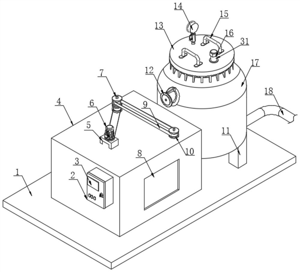
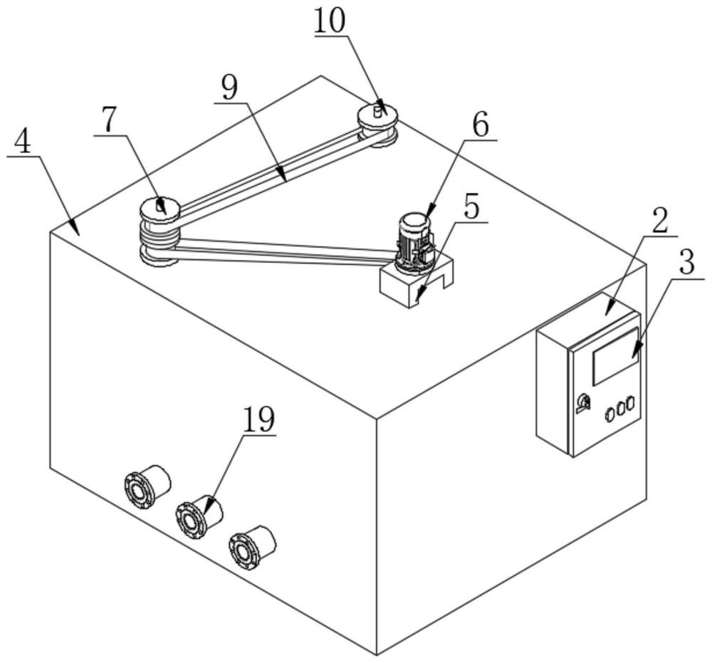
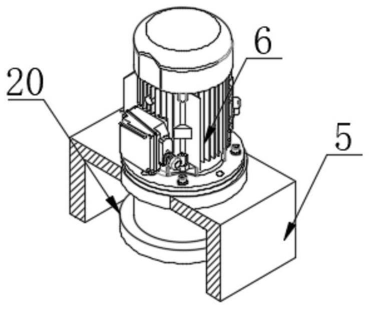
[0042] see Figure 1-Figure 7 , the present invention provides a technical solution:

[0043] A gas shielded refining furnace with waste heat recovery, comprising: a bottom plate 1, a waste heat recovery mechanism, a detection control mechanism, and a drive mechanism;

[0044] Wherein, the waste heat recovery mechanism is installed on the top of the bottom plate 1 , the detection control mechanism is installed in the waste heat recovery mechanism, and the dri...


PUM


Abstract

The invention discloses a gas protection type refining furnace with a waste heat recovery function. The gas protection type refining furnace comprises a bottom plate, a waste heat recovery mechanism, a detection control mechanism and a driving mechanism. The waste heat recovery mechanism is mounted at the top of the bottom plate, and the waste heat recovery mechanism is used for recovering heat generated when the refining furnace is used When the scheme is used, heat generated when the refining furnace is used is recycled through a plurality of heat conduction pipes through the waste heat recycling mechanism, heat dissipation is prevented by installing shells outside the heat conduction pipes, and after the heat reaches the interior of a box body, a motor in a driving mechanism is started to drive a third belt wheel to drive a transmission belt to operate, so that the rotation of a first belt wheel and a second belt wheel is realized; and a rotating rod body is used for driving a plate body to rotate in the box body, so that hot gas circulates in the box body, the exchange efficiency of a heat exchanger is improved, and therefore the waste heat recovery efficiency is improved.

Description

technical field [0001] The invention relates to the technical field of refining furnaces, in particular to a gas-protected refining furnace with waste heat recovery. Background technique [0002] Refining furnace is a kind of smelting equipment in the thermal processing industry. It is mostly used for the final deoxidation and alloying process of molten steel in ferrous metallurgy. There are different classifications according to different smelting purposes. The common ones are argon-blowing refining furnaces. LF refining furnace, etc. [0003] However, there are still certain problems in the existing technology; [0004] 1. When the existing refining furnace is in use, waste heat recovery technology is usually used for waste heat recovery. However, the existing waste heat recovery usually uses heat conduction pipes for recovery. The process is long, and there is no heat preservation or enhanced heat energy conversion in the temperature transmission process measures, resul...

Claims


Application Information

Patent Timeline
IPC IPC(8): C21C7/06C21C7/00F27D17/00G01D21/02
CPCC21C7/0006C21C7/06F27D17/004G01D21/02Y02P10/25
Inventor 吕文灶
Owner 吕文灶
Learn More