Supercharge Your Innovation With Domain-Expert AI Agents!

Terminal electrolysis-resistant coating design method

A technology of electrolytic plating and design method, applied in the direction of coating, superimposed layer plating, metal material coating process, etc., can solve the problem of failure to become a direction, and achieve the effect of outstanding electrolytic resistance and delaying electrolysis time.

Pending Publication Date: 2021-08-06
东莞市川富电子有限公司
View PDF4 Cites 0 Cited by
  • Summary
  • Abstract
  • Description
  • Claims
  • Application Information

AI Technical Summary

Problems solved by technology

[0003] Among the metal materials used for various coatings, stainless steel 316L and titanium materials have good corrosion resistance. Titanium is corrosion-resistant in oxidizing, neutral and weakly reducing media, but in the field of electrical connectors, attention should be paid to resistance. The rate, titanium and oxygen have a great affinity, in the air or in the medium containing oxygen, the surface of titanium forms a layer of dense, strong adhesion, high inert oxide film, although it protects the titanium substrate from corrosion, but there is The titanium oxide film cannot meet the resistivity requirements of electrical conduction (50m ohm); and the stainless steel base material exposed and placed in water will quickly produce an oxide film on the surface; so the stainless steel coating and titanium coating need to be plated on the substrate Covering other metals that meet the resistivity can form a circuit terminal that meets the resistivity
Rhodium, platinum, gold, palladium, and silver are precious metals. In terms of impedance, atmospheric corrosion resistance, and hardness, rhodium, platinum, palladium, and their hardened microalloys with gold are suitable for the outermost material layer of electrical connectors. Necessary, but due to the cost of precious metals, the use of a single precious metal material as an electrical connection device has not become the direction

Method used


Image

  • Terminal electrolysis-resistant coating design method
  • Terminal electrolysis-resistant coating design method
  • Terminal electrolysis-resistant coating design method

Examples


Embodiment Construction

[0032] The specific embodiment of the present invention is introduced.

[0033] A terminal electrolytic plating resistant design method, comprising the following steps:

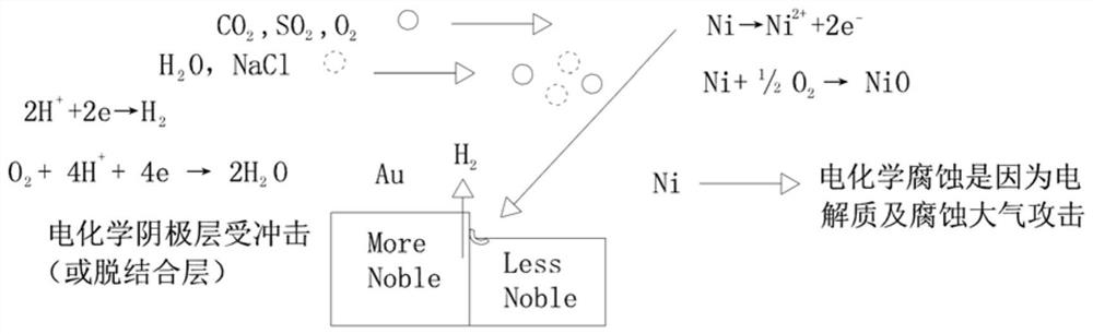
[0034] 1) Choose a non-passivated metal as the base material, and set a multi-layer combined coating on the base material to form an electrolysis-resistant whole; wherein, the hardness of the whole is greater than 168HV, the hardness of the base material is not less than 155HV, and the hardness of each coating is Not less than 120HV, and the hardness of the outermost coating is 400-1000HV;

[0035] 2) Designing a coating sequence to improve the interlayer binding force of the combined coating, starting from the anodic phase coating on the base material, and sorting the coatings according to the positive and increasing standard potential of the metal electrode;

[0036] 3) Design the protective coating to protect the base material, and use the metal coating of the anode phase as the protective coating of the ...


PUM

PropertyMeasurementUnit
Hardnessaaaaaaaaaa
Hardnessaaaaaaaaaa
Hardnessaaaaaaaaaa

Abstract

The invention relates to a terminal electrolysis-resistant coating design method. The method comprises the following steps that (1) non-passivated metal is selected as a base material, and multiple layers of combined coatings are arranged on the base material to form an electrolysis-resistant whole; (2) the coatings are ranked in a forward progressive increase mode according to the standard potential of a metal electrode from an anode phase coating on the base material; (3) the metal coating of the anode phase is used as a protective coating of the base material; the base material is used as a cathode and is electrochemically protected, and the metal coating of the anode phase is used as a first direct contact phase to cover the base material; (4) electrolysis-resistant metal with chemical stability is selected to form an outermost coating; (5) metal with high chemical stability is selected to form a secondary outer coating; and (6) each anode phase coating is thickened. The combined coating designed through the method is outstanding and excellent in electrolysis resistance, all the coatings are ranked according to forward progressive increase of the standard potential of the metal electrode, the metal coating of the anode phase serves as the protective coating of the base material, and the electrolysis time can be delayed.

Description

technical field [0001] The invention relates to the corrosion and protection technology of material science, which is applied to the field of anti-corrosion functional terminals and components requiring electrolysis, and in particular relates to a method for designing a terminal electrolytic plating layer. Background technique [0002] With the development of the market and the upgrading of product technology, more and more consumers are not only limited to the multi-function of the product, but also pursue a fashionable appearance and a small and thin shape. Among them, the pogo pin as a connector has obvious Advantages, but widely used, during the use of pogo pins, they will be attacked by the electrolyte liquid + electrolytic current in the use occasion, and the terminals of the connector are urgently required to be resistant to electrolysis. In order to ensure that the terminal plating is stable, reliable and resistant to electrolysis, targeted Design, and currently ther...

Claims


Application Information

Patent Timeline
IPC IPC(8): C23C28/02C23C28/00C25D5/10
CPCC23C28/023C23C28/321C23C28/34C23C28/021C25D5/10
Inventor 李代文李政宇
Owner 东莞市川富电子有限公司
Features
  • R&D
  • Intellectual Property
  • Life Sciences
  • Materials
  • Tech Scout
  • Unparalleled Data Quality
  • Higher Quality Content
  • 60% Fewer Hallucinations
Learn More