Construction method of double-liquid rapid-hardening high-pressure jet grouting pile

A technology of high-pressure jet grouting piles and construction methods, which is applied to drilling equipment and methods, sheet pile walls, earthwork drilling and mining, etc., which can solve the problems of long slurry solidification time, strong slurry fluidity, and difficulty in forming piles, and achieve Weak fluidity, less dosage, convenient quick-setting pile effect

Pending Publication Date: 2021-08-10
广州捷盈工程有限公司
View PDF5 Cites 1 Cited by
  • Summary
  • Abstract
  • Description
  • Claims
  • Application Information

AI Technical Summary

Problems solved by technology

[0015] Aiming at the conventional rotary grouting piles existing in the prior art, it is difficult to form a pile under the condition of flowing water in the ground, the grout solidification time is long during the ordinary rotary grouting construction process, the fluidity of the slurry is strong, the slurry waste is serious, and the WSS grouting process is easy to lock the drill pipe , work efficiency is very low, the slurry is dispersed and difficult to form piles and other deficiencies, the technical problem to be solved by the present invention is to provide a method that uses water glass and cement slurry to be sprayed in a ratio of 2:1, and the slurry is mixed after spraying. Finally, it can solidify into a pile within 2 minutes, saving construction time, avoiding the waste of cement slurry, and saving raw materials. Moreover, the double-liquid quick-setting high-pressure rotary grouting pile adopts a multi-functional large drilling rig, and its power is large enough to effectively solve the problem of rapid setting of the slurry. Double-fluid rapid-setting high-pressure rotary grouting piles with difficult problems such as drilling

Method used


Image

  • Construction method of double-liquid rapid-hardening high-pressure jet grouting pile
  • Construction method of double-liquid rapid-hardening high-pressure jet grouting pile
  • Construction method of double-liquid rapid-hardening high-pressure jet grouting pile

Examples


Embodiment 1

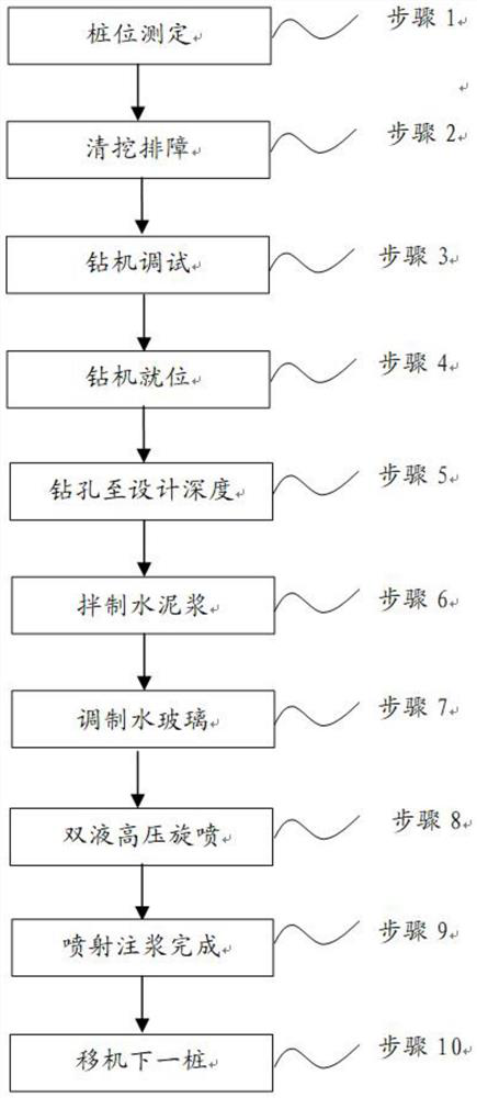
[0080] Regarding the construction process of the quick-setting pile of the double-liquid quick-setting high-pressure rotary grouting pile of the present invention, it specifically includes the following steps:

[0081] Step 1) Pile position measurement: measure the construction axis of the double-liquid rapid-setting high-pressure jet grouting pile through the level meter distance measuring system, and conduct a recheck line inspection. After confirming that the construction axis is qualified, use the steel ruler and the axis to lay out the pile position and use bamboo nails Each pile position corresponds to a piece of bamboo, so that the displacement deviation of the center of the pile hole is less than 20mm, and the determination of the pile position is completed;

[0082] Step 2) Excavation and obstacle removal: Excavate and clear the above-ground and underground obstacles that appear on the construction site, and set up slurry drainage ditches at the same time, and relocate...

Embodiment 2

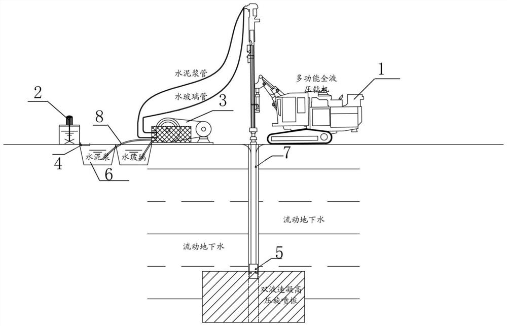
[0092] In the present invention, two pressure gauges are installed above the variable frequency high pressure pump 3, wherein the pressure of the pressure gauges can reach 30 MPa, and safety valves are installed on both sides of the frequency variable high pressure pump 3. When grouting, when the pressure in the variable frequency high pressure pump 3 When it exceeds 45MPa, the safety valve will automatically open to release the pressure, thereby protecting the equipment. Before the grouting, the operators in the background must adjust the ratio of water glass and cement according to the needs of the site, and then start the grouting after the experiment , Observe the flow rate of the pressure gauge and the slurry suction pipe 8. The slurry suction pipe 8 must use a transparent steel wire bellows to observe the situation of the slurry in the slurry suction pipe 8. If there is any situation, immediately communicate with the front desk operator and deal with it quickly.

Embodiment 3

[0094] The quick-setting pile of the double-liquid quick-setting high-pressure rotary grouting pile of the present invention can be applied to the horizontal reinforcement of the tunnel door before the hole is broken. It will be safer to do horizontal occlusal reinforcement on the top of the tunnel to avoid water leakage and collapse of the vault when the hole is broken. In dangerous situations, such as quicksand and other special strata, install the anti-reverse flange device at each hole before construction. If the construction of the pipe shed cannot be successfully broken due to poor grouting effect, it needs to be installed in the middle of the pipe shed. After the construction of horizontal high-pressure quick-forming piles is reinforced, it is convenient for the safety when the hole is broken.


PUM


Abstract

The invention discloses a construction method of a double-liquid rapid-hardening high-pressure jet grouting pile. The construction method comprises the following steps of measuring a pile position, clearing, excavating and removing a fault, debugging a drilling machine, placing the drilling machine in place, drilling to a designed depth, mixing cement paste, preparing water glass, performing double-liquid high-pressure jet grouting, finishing jet grouting, moving the drilling machine to a next pile and the like. Compared with a traditional common jet grouting pile construction process, two nozzles below a multifunctional full-hydraulic drill pipe machine are used for spraying cement paste and water glass through a pump body, then the cement paste solution and water glass solution sprayed out of the nozzles at the bottom of the multifunctional full-hydraulic drill pipe machine are rotationally stirred and mixed at the bottom of a pile position, and therefore rapid hardening and pile forming of the cement paste are achieved; the problem that an ordinary jet grouting pile cannot be formed due to the fact that flowing water exists on the earth surface is solved; and by means of the construction method, rapid pile forming and effective pile forming are achieved through grout, the pile forming time is very short, the liquidity of the grout is weak, the using amount of cement paste is relatively small, the using amount of the grout is reduced, and blocking of underground pipelines is avoided.

Description

technical field [0001] The invention relates to the technical field of building engineering construction, in particular to a construction method of a double-liquid rapid-setting high-pressure jet grouting pile applied to emergency rescue, leak plugging, rapid reinforcement of underground engineering, and reinforcement of weak foundations with extremely unstable groundwater. Background technique [0002] The rotary jet grouting method was developed in the 1970s. It was developed on the basis of static pressure grouting and the introduction of hydraulic coal mining technology. Pour cement slurry to form a condensate, so as to achieve the purpose of strengthening the foundation. [0003] Ordinary rotary grouting piles use high-pressure rotating nozzles to spray cement slurry into the soil layer and mix with the soil to form a continuous lapped cement reinforcement, thereby strengthening to the surface. However, ordinary rotary grouting piles have some defects: [0004] (1) Due...

Claims


Application Information

Patent Timeline
Patent Type & Authority Applications(China)
IPC IPC(8): E02D5/46E02D3/08E21B7/00E21B7/02E21B10/60
CPCE02D3/08E02D5/46E21B7/00E21B7/02E21B10/60
Inventor 郝以郎
Owner 广州捷盈工程有限公司
Why Eureka
Try Eureka