
Omnibearing analyzing and solving method for jump problem of contactor
A solution, contactor technology, applied in sequence/logic controller program control, instrument, program control, etc., can solve the problems of personal casualties, explosion accidents, etc., achieve less investment, ensure stability, and quick results Effect
- Summary
- Abstract
- Description
- Claims
- Application Information
AI Technical Summary
Problems solved by technology
Method used
Image

Examples
Embodiment Construction
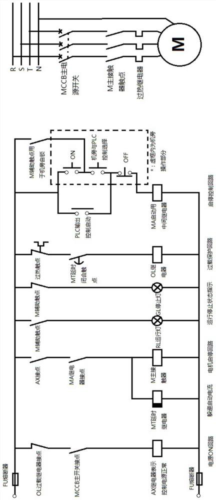
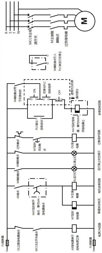
[0020] The comprehensive analysis and solution method for the contactor anti-jumping problem of the present invention will be further described in detail below in conjunction with the accompanying drawings.
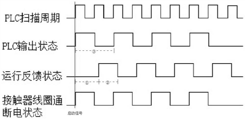
[0021] Such as figure 1 As shown, it is a schematic diagram of overlapping curves between the program scanning period and the motor operation reverse sequence in the present invention.
[0022] From figure 1 It can be seen from the figure that if the scan period in the on-site PLC program is set to 200MS, when the start signal comes, the motor running feedback signal is transmitted to the PLC by the normally open contact of the relay. There will be a delay closure. When the delay time is greater than 200MS and less than 300MS, the feedback signal received by the PLC will be delayed and turned into "1" at the same time, as shown in Figure ①, and the output of the PLC will be turned from "1" to "0" state output . When the next scan cycle comes, although the relay receive...
PUM
 Abstract
Description
Claims
Application Information