Multi-stage partitioned combustion structure for gas turbine

A technology of gas turbine and combustion structure, applied in the direction of combustion chamber, combustion method, combustion equipment, etc., can solve the problems that combustion stability and low emission can not be well balanced, achieve flameout performance and low emission, ensure high-efficiency combustion, reduce The effect of small NOx emissions

Active Publication Date: 2021-08-13
成都中科翼能科技有限公司
View PDF17 Cites 4 Cited by
  • Summary
  • Abstract
  • Description
  • Claims
  • Application Information

AI Technical Summary

Problems solved by technology

[0005] In order to solve the problem that the combustion stability and low emission cannot be well balanced in the combustion process of gas turbines in the prior art, this solution provides a multi-stage partitioned combustion structure for gas turbines. The combustion area of ​​the combustion chamber Multi-level zoning

Method used


Image

  • Multi-stage partitioned combustion structure for gas turbine
  • Multi-stage partitioned combustion structure for gas turbine
  • Multi-stage partitioned combustion structure for gas turbine

Examples


Example Embodiment

[0038] Example 1

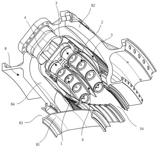
[0039] like Figure 1 - Figure 7 As shown, the present embodiment is designed for a multi-stage partition combustion structure for a gas turbine, including a combustion chamber casing 8, a flame barrel 5, a plurality of swirl devices, and a splitter 6.

[0040] The combustion chamber casing 8 has an annular groove cavity 84; the outlet of the lucacea 84 towards the rear side of the gas turbine. And the combustion chamber casing 8 is used in the mounting of the flame bar 5.

[0041] The flame bar 5 is disposed in the lumen 84 of the combustion chamber casing 8, which has a loop-shaped combustion chamber. The combustion outlet 54 of the combustion chamber is the same as the outlet of the lumen 84 of the combustion chamber casing 8; the gas is discharged from the combustion outlet 54 after the flame bar 5 is burned.

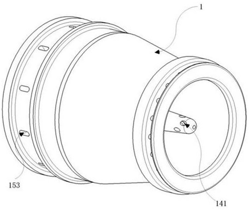
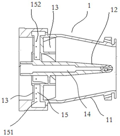
[0042] The combustion chamber of the swirl is used to introduce air and gas into the combustion chamber; each cyclone includes a swirling shell 11, a ...

Example Embodiment

[0051] Example 2

[0052] In this example, a plurality of working modes are designed in the multi-level partition-type combustion structure for gas turbines in the first embodiment, which are ignition state mode, small state mode, transition status working mode, and large load state mode of operation, four The working mode is divided by the operating mode of each cyclone group.

[0053] When the ignition state mode is modeled, the various swirl groups are only transmitted from the second gas passage 14 of the value class swirl 1, and the principle of the ignition state mode of operation is: when this mode of operation, the gas supply amount And the amount of intake is small, and the emissions of the emission standard do not specify and require, all the gas is concentrated at a duty cyclone 1, and sprayed by the second gas passage 14 of the duty cyclone 1, using diffusion The advantage of high stability of combustion enables the combustion chamber to obtain a hydride ratio combusti...

Example Embodiment

[0057] Example 3

[0058] like Figure 1 - Figure 7 As shown, based on the structure of Example 1, the present embodiment refines the structure of the flame barrel 5 and the main body 82.

[0059] The flame barrel 5 includes a rear segment 52 and a cylinder front section 51, the cylindrical front section 51 is a double layer structure, the inner layer is the front interior wall 513, the outer layer is the front section of the outer wall 513, and there is a sandwich channel between the front interior wall 513 514. A impact cooling hole 511 is provided at the outer wall of the cylinder front section 51, and the mounting portion 53 for mounting the swirl device is provided in the inner bottom portion of the cylinder front section 51.

[0060] A slit groove is provided in the inside of the cartridge, and the slot is provided toward the combustion outlet 54 and the bottom of the slot of the slot, and the slot cooling hole 521 outside the rear section 52 is provided, and the slot cooling...


PUM


Abstract

The invention belongs to the technical field of gas turbines, and particularly relates to a multi-stage partitioned combustion structure for a gas turbine. The multi-stage partitioned combustion structure for the gas turbine comprises a combustion chamber casing, a flame tube, a plurality of cyclones and a diverter. The cyclones are divided into an on-duty cyclone, a flame transfer cyclone, a first main combustion cyclone and a second main combustion cyclone, each cyclone is provided with a first fuel gas channel, and the first fuel gas channels convey fuel gas used for premixed combustion. A second fuel gas channel is further arranged at the on-duty cyclone, and the second fuel gas channel is used for conveying fuel gas for diffusive combustion. The installation angles of blades of the cyclones are different, and the flow fields of rotating airflow generated by the cyclones are relatively independent, so that the cyclones participate in independent partitioned combustion. According to the multi-stage partitioned combustion technology in the scheme, the four stages of different cyclones are combined with the diverter, multi-stage partitioned organization combustion is formed in a staged fuel supply mode, the requirements of all working conditions are met, the ignition and flameout performance and combustion stability of a combustion chamber are guaranteed, and the requirement for low emission of nitric oxide is met.

Description

Technical field [0001] The present invention belongs to the technical field of gas turbine, and more particularly to a multi-stage partition-type combustion structure for a gas turbine. Background technique [0002] Gas turbine is a good cleaning, high efficiency, has advantages of small size, low weight, and is widely used in power generation, independent energy systems, mechanical drives and other fields. However, the gas turbine produces nitrogen oxides during the working process (NO x ), Carbon monoxide (CO) and contaminants such as hydrocarbon compound (UHC), the formation of the above contaminants, the main and combustion of the combustion flame temperature, equivalent ratio, intake pressure, and mixed uniformity of air and air, etc. related. [0003] In recent years, the development of low-emissions combustion technology has developed rapidly, and various new technologies have emerged, and a group of low-emission combustion technology has developed a variety of low polluti...

Claims


Application Information

Patent Timeline
IPC IPC(8): F23R3/38F23R3/42F23R3/16F23R3/28
CPCF23R3/16F23R3/283F23R3/38F23R3/42
Inventor 刘宝琪范珍涔颜腾冲王龙陈柳君代茂林杨治王梁丞赵汝伟
Owner 成都中科翼能科技有限公司
Why Eureka
Try Eureka