Field detection equipment based on residual liquid petroleum pipeline flaw detection operation

A technology for on-site detection of oil pipelines, applied in measuring devices, using sound waves/ultrasonic waves/infrasonic waves to analyze solids, using sound waves/ultrasonic waves/infrasonic waves for material analysis, etc. The impact of the measurement effect and other issues can be achieved to shorten the detection time, ensure the detection efficiency and improve the detection accuracy

Inactive Publication Date: 2021-08-13
陈美华
View PDF0 Cites 2 Cited by
  • Summary
  • Abstract
  • Description
  • Claims
  • Application Information

AI Technical Summary

Problems solved by technology

[0003] In ultrasonic flaw detection, the ultrasonic probe emits pulse waves into the test piece, and the method of detecting pipeline defects according to the reflected wave is called the pulse reflection method. The pulse reflection method includes the defect echo method, the bottom wave height method and the multiple times Bottom wave method is currently a cost-effective method. In the random inspection of oil pipelines, there is a certain amount of residual liquid inside the pipeline after transportation, including crude oil, processed oil and other residual liquids. Inside the pipe wall, it is easy to cause difficulty in walking the existing flaw detection equipment and flaw detection robots. At the same time, foreign objects may have a certain impact on the effect of flaw detection measurement, and cause excessive detection errors

Method used


Image

  • Field detection equipment based on residual liquid petroleum pipeline flaw detection operation
  • Field detection equipment based on residual liquid petroleum pipeline flaw detection operation
  • Field detection equipment based on residual liquid petroleum pipeline flaw detection operation

Examples


Embodiment Construction

[0024] The present invention will be described in detail below in conjunction with the appended drawings, and the technical solutions in the embodiments of the present invention will be clearly and completely described. Obviously, the described embodiments are only some of the embodiments of the present invention, not all of them. Based on the embodiments of the present invention, all other embodiments obtained by persons of ordinary skill in the art without making creative efforts all belong to the protection scope of the present invention; in addition, the terms "first", "second", "Third", "Up, Down, Left, Right", etc. are used for descriptive purposes only and are not to be construed as indicating or implying relative importance. At the same time, in the description of the present invention, unless otherwise clearly stipulated and limited, the terms "connected" and "connected" should be understood in a broad sense, for example, it can be a fixed connection, a detachable conn...


PUM


Abstract

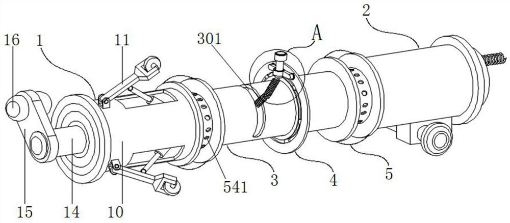
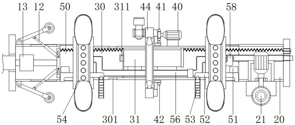
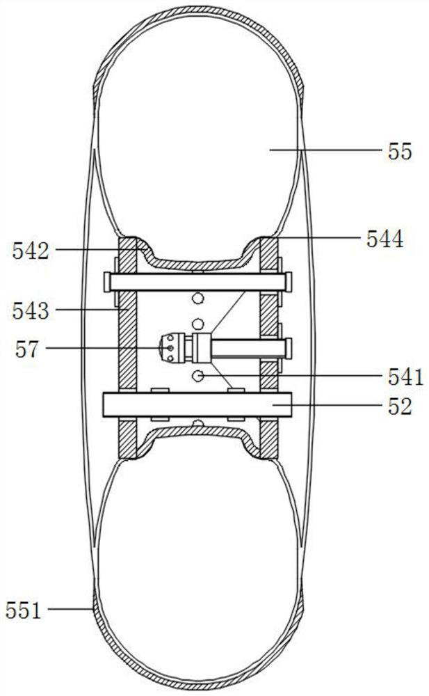
The invention discloses field detection equipment based on residual liquid petroleum pipeline flaw detection operation, and relates to the technical field of detection equipment, the field detection equipment comprises a power joint, the power joint is composed of a tail cavity and a driving wheel, the tail cavity is hollow, the driving wheel is installed at the bottom of the tail cavity, and the front end of the power joint is respectively provided with a detection joint and a forward joint; the power joint is connected with the forward joint through the detection joint, the detection mechanism is installed in the middle of the detection joint, power is strong and controllable, the equipment can effectively adapt to walking of petroleum pipelines to be detected within specifications, meanwhile, the environment where the detection joint is located is kept relatively dry, and thus it is guaranteed that the detection mechanism can work in the better environment, the detection precision is improved, errors are reduced, the detection mechanism effectively ensures accurate butt joint with the weld joint of the to-be-detected pipeline, the detection efficiency is ensured to a certain extent, and the detection time is also shortened.

Description

technical field [0001] The invention relates to the technical field of testing equipment, in particular to an on-site testing equipment based on residual liquid oil pipeline flaw detection. Background technique [0002] The purpose of pipeline flaw detection is to check whether the internal quality of the weld seam of the pipeline welding joint is qualified. Radiographic flaw detection is a flaw detection method that uses rays to penetrate objects to find internal defects. Among them, rays and ultrasonic waves are widely used in pipeline flaw detection operations, but ray flaw detection has Certain radioactivity, with the development of science and technology, most non-destructive testing methods can be used for pipelines, such as: ray, ultrasonic, magnetic particle, penetration, eddy current, guided wave, TOFD, phased array, etc. [0003] In ultrasonic flaw detection, the ultrasonic probe emits pulse waves into the test piece, and the method of detecting pipeline defects ac...

Claims


Application Information

Patent Timeline
Patent Type & Authority Applications(China)
IPC IPC(8): G01N29/04G01N29/265
CPCG01N29/04G01N29/048G01N29/265G01N2291/023
Inventor 金诚
Owner 陈美华
Why Eureka
Try Eureka