
Bilateral LC compensation type CPT system and parameter design method thereof

A double-sided, capacitor compensation technology, applied in control/regulation systems, design optimization/simulation, geometric CAD, etc., can solve the problem of ignoring the composition design of compensation capacitors, to ensure power transmission capability, meet high reliability, and avoid ignition effect of the problem

Active Publication Date: 2021-08-13
NANJING UNIV OF AERONAUTICS & ASTRONAUTICS +1
View PDF1 Cites 2 Cited by
  • Summary
  • Abstract
  • Description
  • Claims
  • Application Information

AI Technical Summary

Problems solved by technology

In addition to the safety issue of plate voltage stress, efficiency and power density are also key challenges in the practical application of CPT systems
The existing design methods are difficult to take into account the optimization requirements of voltage stress, efficiency and power density at the same time, and ignore the composition design of the compensation capacitor

Method used


Image

  • Bilateral LC compensation type CPT system and parameter design method thereof
  • Bilateral LC compensation type CPT system and parameter design method thereof
  • Bilateral LC compensation type CPT system and parameter design method thereof

Examples


Embodiment 1

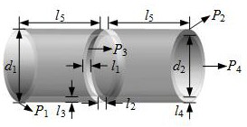
[0054] Such as figure 1 As shown, the present invention provides a bilateral LC compensation type CPT system, the bilateral LC compensation type CPT system includes a DC power supply 1, a high frequency inverter circuit 2, a compensation network 3, a capacitive coupling mechanism 4, a rectification filter circuit 5 and a load R o 6; The compensation network includes the primary side series compensation inductance L 1 , primary parallel compensation capacitor C e1 , Secondary side series compensation inductance L 2 and the secondary parallel compensation capacitor C e2 ;Primary parallel compensation capacitor C e1 Parallel compensation capacitor with secondary side C e2 Same; primary side series compensation inductance L 1 Parallel compensation capacitor with the primary side C e1 Series connection; secondary series compensation inductance L 2 Parallel compensation capacitor with secondary side C e2 Series connection; capacitive coupling mechanism includes pr...

Embodiment 2

[0069] The further design of this embodiment is that when the rectification and filtering circuit is a bridge rectification circuit, and the diode parasitic capacitance is not considered C D effect, the rectifier filter circuit and load R o The equivalent resistance value of R eq The expression for is as follows:

[0070]

[0071] Or when the rectifier filter circuit is a bridge rectifier circuit, and the diode parasitic capacitance is considered C D effect, the rectifier filter circuit and load R o The equivalent resistance value of R eq The expression for is as follows:

[0072]

[0073] In the formula, R eq For the rectifier filter circuit and load R o The equivalent resistance value; C D is the capacitance value of the diode parasitic capacitance.

Embodiment 3

[0075] The further design of this embodiment is that the primary side series compensation inductance L 1 and secondary series compensation inductance L 2 Calculated according to the formula:

[0076]

[0077] In the formula, C s1 is the self-capacitance of the primary side of the capacitive coupling mechanism, C e1 is the parallel compensation capacitor on the primary side, C s2 is the self-capacitance of the secondary side of the capacitive coupling mechanism; C e2 Parallel compensation capacitor for the secondary side; f is the resonant frequency.


PUM


Abstract

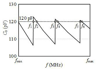
The invention discloses a bilateral LC compensation type CPT system and a parameter design method thereof. Under the size limitation of any given output power Po, output load Ro and capacitive coupling mechanism, the bilateral LC compensation type CPT system can simultaneously realize the minimum voltage stress, the optimal AC-AC efficiency and the minimum number of capacitors, and facilitates the development demand of the CPT system in a miniaturized application occasion. According to the parameter design method, the resonant frequency is designed, the voltage stress of the capacitive coupling mechanism is limited within a reasonable design range, and the sparking problem caused by air breakdown between metal polar plates is avoided while the power transmission capacity is ensured.

Description

Technical field: [0001] The invention relates to a CPT system suitable for bilateral LC compensation and a parameter design method thereof, which belongs to the field of electric energy conversion and can be applied to miniaturized wireless charging occasions such as portable electronic equipment, mechanical arms, and inertial turntables. Background technique: [0002] Wireless Power Transfer (WPT for short) is widely used in electric vehicle charging, rail transit, high-speed rotating equipment power supply, high-voltage power line power supply, underground pipeline due to its advantages of no contact failure, convenient use, good mobility and easy maintenance. It has been widely used in network detection, implanted equipment and power supply of measurement and control equipment. Among them, Inductive Power Transfer (IPT for short) and Capacitive Power Transfer (CPT for short) have become two important research directions in WPT technology due to their large transmission po...

Claims


Application Information

Patent Timeline
Patent Type & Authority Applications(China)
IPC IPC(8): H02J50/05H02M5/08H02M3/335G06F30/17G06F30/20
CPCG06F30/17G06F30/20H02M3/33523H02M5/08H02J50/05Y02B70/10
Inventor 吴羽温振霖殷金安徐立刚陈乾宏任小永张之梁
Owner NANJING UNIV OF AERONAUTICS & ASTRONAUTICS
Learn More