Piston air compressor pump head assembling machinery and assembling method

A technology of air compressors and pump heads, which is applied in the direction of workpiece clamping devices, metal processing, metal processing equipment, etc., can solve problems such as low efficiency, difficult pump head shells, and continuous operations that are difficult to mass-produce, so as to reduce shaking The possibility of deflection, the improvement of work efficiency, and the effect of stable clamping work

Inactive Publication Date: 2021-08-17
陈新海
View PDF0 Cites 3 Cited by
  • Summary
  • Abstract
  • Description
  • Claims
  • Application Information

AI Technical Summary

Problems solved by technology

[0004] 1. In the process of assembling the pump head of the compressor, it is often necessary for multiple people to manually support the pump head shell and the pump head base, and then install it. This operation method is inefficient and difficult to quickly and accurately Align and install the installation holes between the pump head base and the pump head housing, and the sharp edges on the pump head base and the housing are also likely to cause injury to the worker's body, and it is difficult to carry out batch continuous operation. Reduced the operating efficiency of the piston air compressor pump head production and processing operations;
[0005] 2. During the assembly process of the pump head of the traditional piston air compressor, it is difficult to adapt to the change of the outer wall of the pump head base and provide it with multi-station stable clamping operations, which increases the mechanical vibration and causes the pump head base to shake and deviate. It is also difficult to stably clamp the pump head shell while maintaining the same height at both ends of the pump head shell, which increases the difficulty of positioning the installation hole

Method used


Image

  • Piston air compressor pump head assembling machinery and assembling method
  • Piston air compressor pump head assembling machinery and assembling method
  • Piston air compressor pump head assembling machinery and assembling method

Examples


Embodiment Construction

[0035] In order to make the technical means realized by the present invention, creative features, goals and effects easy to understand, the following combination Figure 1 to Figure 10 , to further elaborate the present invention.

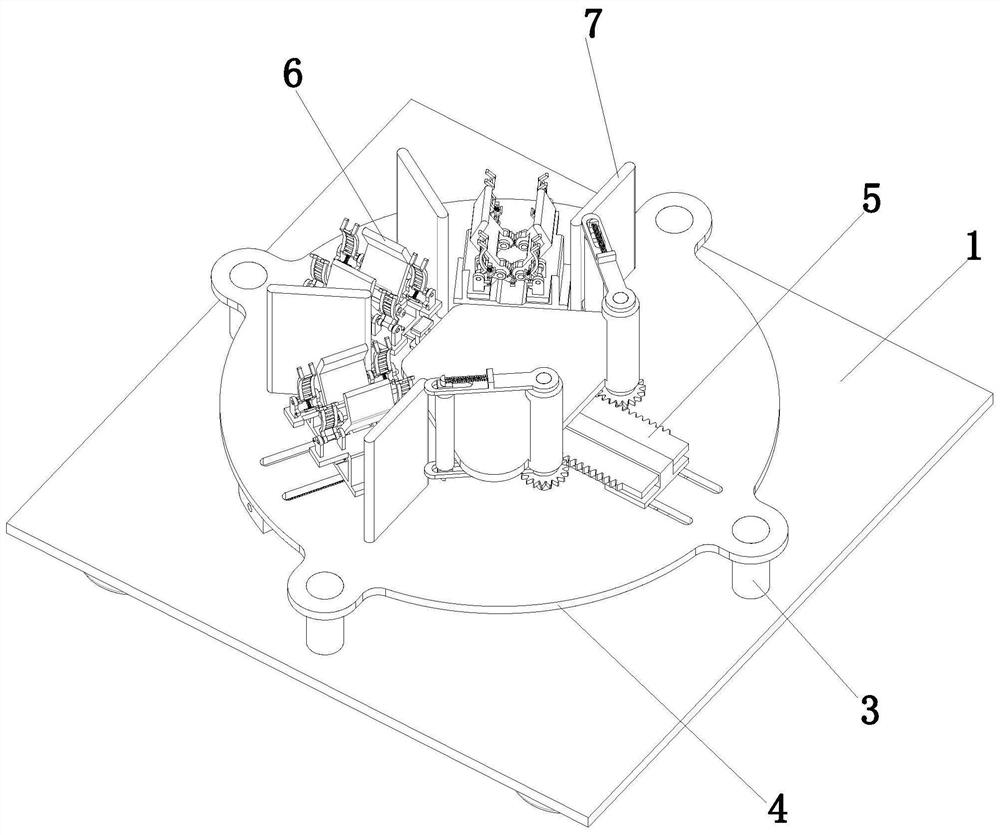
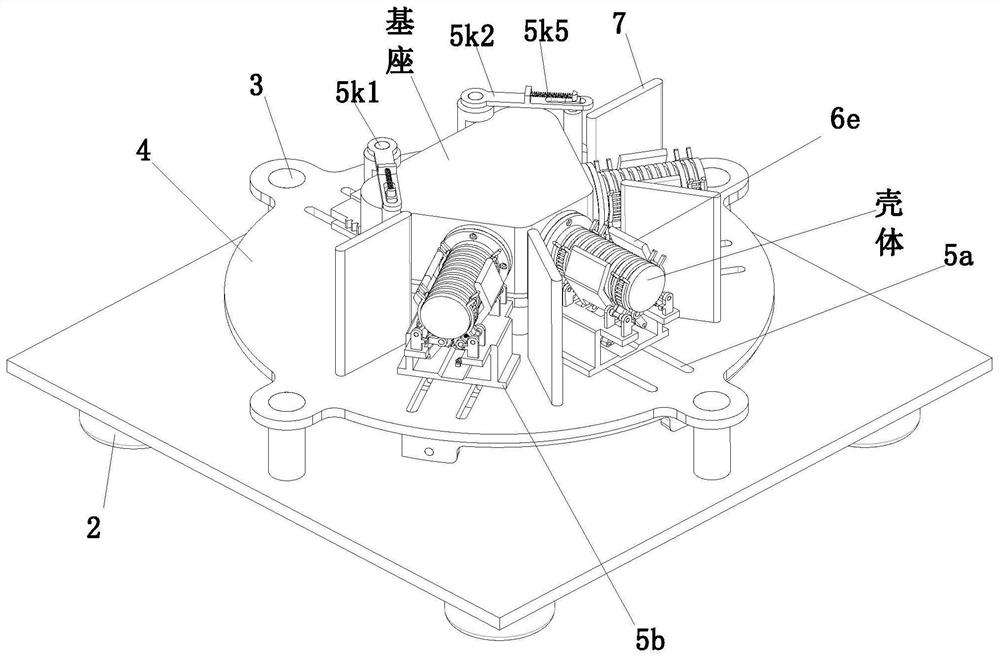
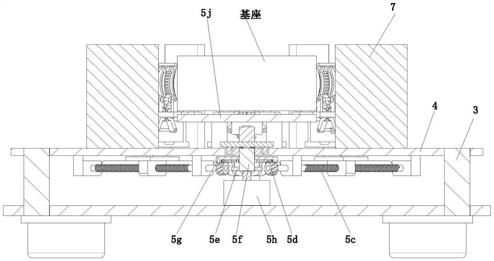
[0036] A pump head assembly machine for a piston air compressor, comprising a mounting base plate 1, a supporting foot 2, a supporting rod 3, a supporting plate 4, a positioning mechanism 5 and a clamping mechanism 6, and the corners around the lower end surface of the mounting base plate 1 are evenly installed There are support feet 2, support rods 3 are evenly installed at the corners around the upper end surface of the installation base plate 1, support discs 4 are installed on the upper ends of the support rods 3, positioning mechanisms 5 are installed on the support disc 4, and multiple A clamping mechanism 6 is assembled, and the clamping mechanism 6 is connected with the positioning mechanism 5 .

[0037] The positioning mechanism 5 include...


PUM


Abstract

The invention provides piston air compressor pump head assembling machinery and an assembling method. The piston air compressor pump head assembling machinery comprises a mounting bottom plate, supporting legs, supporting rods, a supporting disc, a positioning mechanism, clamping mechanisms and partition plates. By means of the piston air compressor pump head assembling machinery and the assembling method, the problems that piston air compressor pump head assembling operations are difficult to adapt to the radian change of the outer wall of a pump head base seat, and multi-station stable clamping operations can not be provided for the pump head base seat, the possibility that the pump head base seat shakes and deflects due to mechanical vibration is increased, the heights of the two ends of a pump head shell are also difficult to keep consistent while the pump head shell is stably clamped, mounting hole positions between the pump head base seat and the pump head shell are difficult to be quickly and accurately aligned and mounted, batch continuous operations are difficult to perform, and the operation difficulty of the positioning operations of the mounting hole positions is increased can be solved.

Description

technical field [0001] The invention relates to the technical field of pump head assembly, in particular to a piston air compressor pump head assembly machine and assembly method. Background technique [0002] The pump head of the piston air compressor is the core component of the piston air compressor. The reciprocating motion of the piston in the pump head is formed by the crank slider mechanism driven by the electric motor. The rotary motion of the crank is converted into the reciprocating motion of the piston. When the piston in the piston air compressor is reciprocating, a pressure difference will be generated in the pump head, and further work will be done externally through the suction valve and exhaust valve. A compressor of this structure always has a residual volume at the end of the exhaust process. During the next inhalation, the compressed air in the remaining volume will expand, thereby reducing the amount of inhaled air and increasing the compression work. S...

Claims


Application Information

Patent Timeline
Patent Type & Authority Applications(China)
IPC IPC(8): B23P19/00B23P19/06B25B11/02
CPCB23P19/001B23P19/06B25B11/02
Inventor 陈新海
Owner 陈新海
Why Eureka
Try Eureka