Eureka AIR delivers breakthrough ideas for toughest innovation challenges, trusted by R&D personnel around the world.

Filtering system and filtering method

A filtration system and filtration tower technology, applied in filtration treatment, control/manipulation systems, chemical instruments and methods, etc., can solve problems affecting work efficiency, increasing work cost, affecting precipitation quality, etc., to improve work efficiency and save time Cost, the effect of increasing the filter area

Pending Publication Date: 2021-08-17
浙江瑞鸿机电设备有限公司
View PDF7 Cites 0 Cited by
  • Summary
  • Abstract
  • Description
  • Claims
  • Application Information

AI Technical Summary

Problems solved by technology

[0002] The current direct discharge of sewage is easy to pollute the environment, does not conform to the current environmental protection concept, and is unsustainable. Although the current filtration system is getting worse, there are still the following unsatisfactory points:
[0003] 1. At present, the filter components in the filter tower cannot be disassembled;
[0004] 2. At present, the cotton core in the filter member is easy to shrink and become soft after being soaked in water for a long time, which is inconvenient for subsequent use, affects the filtering effect, and increases the working cost at the same time;
[0005] 3. At present, there is no precipitation port in the chemical purification tower, which is inconvenient to put precipitation reagents, which affects the work efficiency of the staff;
[0006] 4. At present, there is no temperature adjustment device in the chemical purification tower, and the precipitation time will be longer, which will affect the work efficiency;
[0007] 5. At present, there is no concentration detector in the chemical purification tower, which cannot realize the automatic injection of precipitant, which increases the workload of the staff. At the same time, the content of added precipitant cannot be guaranteed, which affects the quality of precipitation

Method used


Image

  • Filtering system and filtering method
  • Filtering system and filtering method
  • Filtering system and filtering method

Examples


Embodiment 1

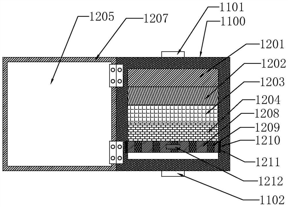
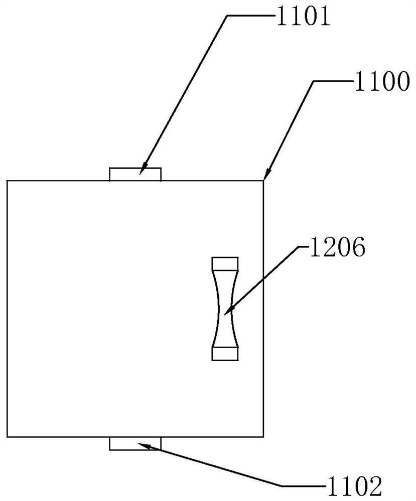
[0055] Such as Figure 1-Figure 4 As shown, the present invention discloses a filter system, including a filter device 1000, characterized in that: the filter device 1000 is set as a filter tower 1100, the top of the filter tower 1100 is provided with a first water inlet 1101, the filter A first water outlet 1102 is provided at the bottom of the tower 1100 , and a filter member 1200 is provided in the filter tower 1100 , and the filter member 1200 is detachable from the filter tower 1100 .

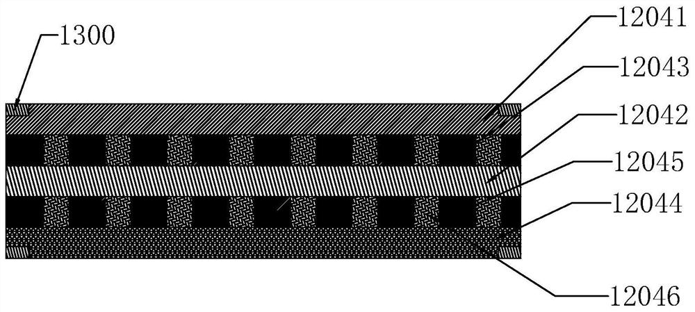
[0056] In a specific embodiment of the present invention, the filter member 1200 is sequentially arranged as activated carbon 1201, quartz sand 1202, anthracite filter material 1203 and filter cotton core 1204 from top to bottom, and a switch is provided on a side wall of the filter tower 1100 Door 1205, the switch door 1205 is hingedly connected with the filter tower 1100, the switch door 1205 is provided with a handle 1206 away from the filter tower 1100, and the handle 1206 is welded on...

Embodiment 2

[0059] Embodiment 2, the difference with embodiment 1 is that

[0060] Such as Figure 5-Figure 8As shown, in a specific embodiment of the present invention, a water level monitoring device 1400 is also provided in the filter tower 1100, and the water level monitoring device 1400 is on the side wall of the filter tower 1100, and the water level monitoring device 1400 is connected to a controller 1401, the controller 1401 is connected with a valve 1402, the valve 1402 is set at the first water inlet 1101, the valve 1402 includes an upper chamber 1403 and a lower chamber 1404, the upper chamber 1403 is close to the The first water inlet 1101 is provided with a filter module 1405, and the filter module 1405 is provided as a non-woven fabric 1405a, and a blocking device 1406 is provided between the upper chamber 1403 and the lower chamber 1404, and the blocking device 1406 includes a column 1407, a column chamber 1408 and a push plate 1409, the controller 1401 is connected to the...

Embodiment 3

[0063] Embodiment 3 is different from Embodiment 2 in that

[0064] Such as Figure 9-Figure 10 As shown, in a specific embodiment of the present invention, the first water outlet 1102 is connected with a chemical purification tower 1700, and the chemical purification tower 1700 includes a second water inlet 1701, a second water outlet 1702, a sewage outlet 1703, a sedimentation Reagent port 1704 and concentration detector 1705, the second water inlet 1701 is arranged at the top of the chemical purification tower 1700, and is connected to the first water outlet 1102, and the precipitation reagent is arranged at the top of the chemical purification tower 1700 top, the second water outlet 1702 is set at the bottom of the chemical purification tower 1700, the sewage outlet 1703 is set at the bottom of the purification tower, and the concentration detector 1705 is set at the inside of the chemical purification tower 1700 At the top, the output end of the concentration detector 17...


PUM


Abstract

The invention relates to the field of filtrating and purification, in particular to a filtrating system which comprises a filtrating device and is characterized in that the filtrating device is arranged to be a filtrating tower, a first water inlet is formed in the top of the filtrating tower, a first water outlet is formed in the bottom of the filtrating tower, and a filtrating component is arranged in the filtrating tower; and the filtering component and the filtering tower are detachable, the filtering component is sequentially provided with activated carbon, quartz sand, an anthracite filtering material and a filtering cotton core from top to bottom, one side wall of the filtering tower is provided with an opening and closing door, the opening and closing door is hinged to the filtering tower, and the side, away from the filtering tower, of the opening and closing door is provided with a handle. The handle is welded to the opening and closing door, and a rubber sealing ring is arranged on the side, close to the filtering tower, of the opening and closing door.

Description

technical field [0001] The invention relates to the field of filtration and purification, in particular to a filtration system and a filtration method. Background technique [0002] The current direct discharge of sewage is easy to pollute the environment, does not conform to the current environmental protection concept, and is unsustainable. Although the current filtration system is getting worse, there are still the following unsatisfactory points: [0003] 1. At present, the filter components in the filter tower cannot be disassembled; [0004] 2. At present, the cotton core in the filter member is easy to shrink and become soft after being soaked in water for a long time, which is inconvenient for subsequent use, affects the filtering effect, and increases the working cost at the same time; [0005] 3. At present, there is no precipitation port in the chemical purification tower, which is inconvenient to put precipitation reagents, which affects the work efficiency of t...

Claims


Application Information

Patent Timeline
Patent Type & Authority Applications(China)
IPC IPC(8): C02F9/04
CPCC02F1/001C02F1/52C02F1/008C02F2209/02C02F2209/42C02F2303/14
Inventor 郑超敏童卫忠
Owner 浙江瑞鸿机电设备有限公司
Why Eureka
Eureka Blog
Learn More