bridge thermal rectifier

A thermal rectifier and bridge technology, which is applied in the field of bridge thermal rectifiers to achieve the effect of improving energy conversion efficiency

Active Publication Date: 2022-06-17
SOUTHEAST UNIV
View PDF10 Cites 0 Cited by
  • Summary
  • Abstract
  • Description
  • Claims
  • Application Information

AI Technical Summary

Problems solved by technology

[0004] The present disclosure provides a bridge-type thermal rectifier, whose technical purpose is to solve the problem of obtaining constant power output from a heat source that changes with time, and can solve the problem of uninterrupted output of stable electric power even in nights without sun or in rainy days when utilizing solar energy , or convert the time-varying waste heat generated by the internal combustion engine, compressor, etc. into a constant electrical power output

Method used


Image

  • bridge thermal rectifier
  • bridge thermal rectifier
  • bridge thermal rectifier

Examples


Embodiment Construction

[0023] The technical solutions of the present disclosure will be described in detail below with reference to the accompanying drawings. In the description of the present invention, it should be understood that the terms "first", "second", "third" and "fourth" are only used for the purpose of description, and should not be construed as indicating or implying relative importance or implicit The number of technical features indicated with the indication is only used to distinguish different components.

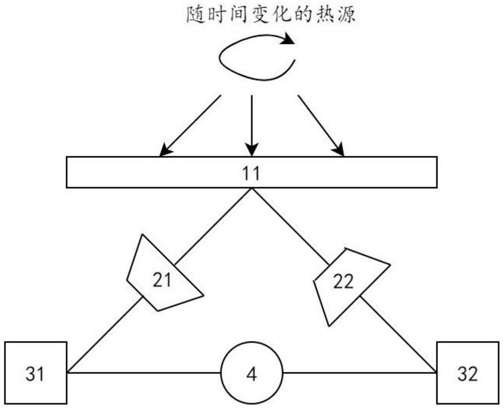
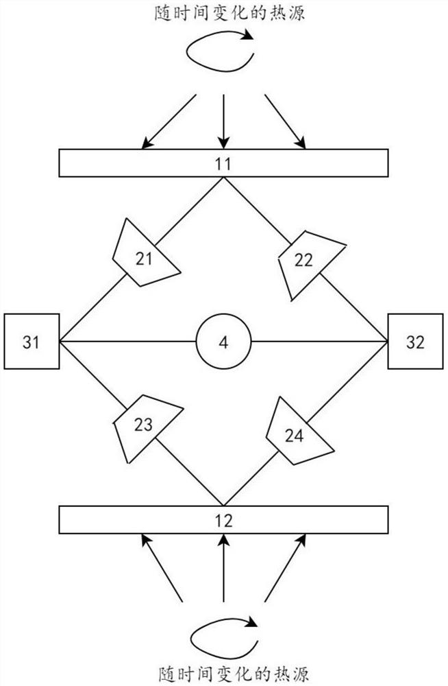
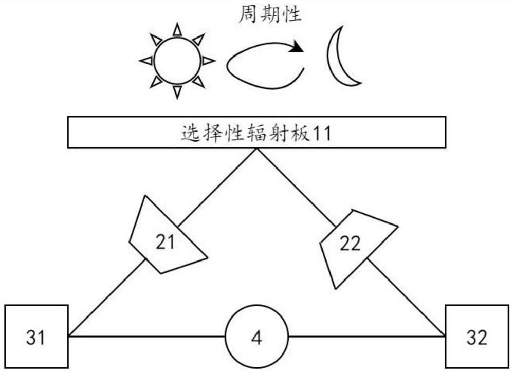
[0024] In addition, the working mechanism of the thermal diode involved in the present invention is as follows: when the direction of the external temperature difference is consistent with the bias direction of the thermal diode, the thermal resistance of the thermal diode is extremely small, which is defined as R Fwd. , the heat flow can quickly transfer from the hot end to the cold end through the thermal diode. When the direction of the external temperature difference is oppos...


PUM


Abstract

The invention discloses a bridge-type bridge-type thermal rectifier, which relates to the technical field of engineering thermophysics and solves the technical problem that a constant power output cannot be obtained from a heat source that changes with time. The main point of the technical solution is to heat the first heat energy absorption / release plate Make it get high temperature, heat the first heat capacity by forward biasing the first heat diode pointing to the first heat capacity, because the second heat diode is reverse biased, the second heat capacity cannot be heated by the first heat energy absorbing / releasing plate , so the first heat capacity will be maintained at a higher temperature, while the second heat capacity will be maintained at a lower temperature. As the heat source weakens, when the temperature of the first heat absorbing / releasing plate continues to drop below the temperature of the second heat capacity, the waste heat obtained by the second heat capacity from the operation of the heat engine can flow through the first heat energy from the second heat diode The absorption / release sheet diffuses to the outside world. After several cycles, the first heat capacity and the second heat capacity will each be maintained at a relatively stable temperature, thereby continuously relying on the heat engine for stable output.

Description

technical field [0001] The present disclosure relates to the technical field of engineering thermophysics, and in particular, to a bridge-type thermal rectifier. Background technique [0002] The existing conversion and utilization of time-varying heat sources (hereinafter referred to as "AC" heat sources) mainly consists of the following forms: (1) Photovoltaic panel power generation technology, which converts solar energy into electrical energy during the day and stores it in a battery for output. ; (2) Solar water heaters absorb solar heat during the day and store it as thermal energy; (3) Thermoelectric effects, including pyroelectric effect and thermoelectric effect, directly convert temperature differences into electrical energy. [0003] The disadvantage of the above three forms is that photovoltaic power generation and water heaters cannot solve the problem of periodic changes in external temperature, for example, they cannot work at night and in cloudy and rainy day...

Claims


Application Information

Patent Timeline
Patent Type & Authority Patents(China)
IPC IPC(8): H02N11/00F03G7/04F03G6/00
CPCH02N11/002F03G7/04F03G6/00Y02E10/46
Inventor 赵晓冬陈震
Owner SOUTHEAST UNIV
Why Eureka
Try Eureka