Hub and barrel-shaped workpiece edge cutting equipment and processing method

A technology for workpiece edge and cutting equipment, applied in welding/cutting auxiliary equipment, metal processing equipment, welding equipment, etc. land area effect

Active Publication Date: 2021-08-20
德州西恩数控设备股份有限公司
View PDF7 Cites 0 Cited by
  • Summary
  • Abstract
  • Description
  • Claims
  • Application Information

AI Technical Summary

Problems solved by technology

[0003] Aiming at the above-mentioned technical problems existing in the prior art, the present invention provides a wheel hub and barrel-shaped workpiece edge cutting equipment and a processing method, which solves the technical problems of low processing efficiency and environmental pollution caused by the processing methods in the prior art

Method used


Image

  • Hub and barrel-shaped workpiece edge cutting equipment and processing method
  • Hub and barrel-shaped workpiece edge cutting equipment and processing method
  • Hub and barrel-shaped workpiece edge cutting equipment and processing method

Examples


Embodiment 1

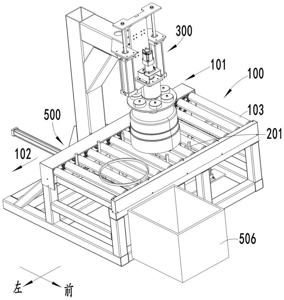
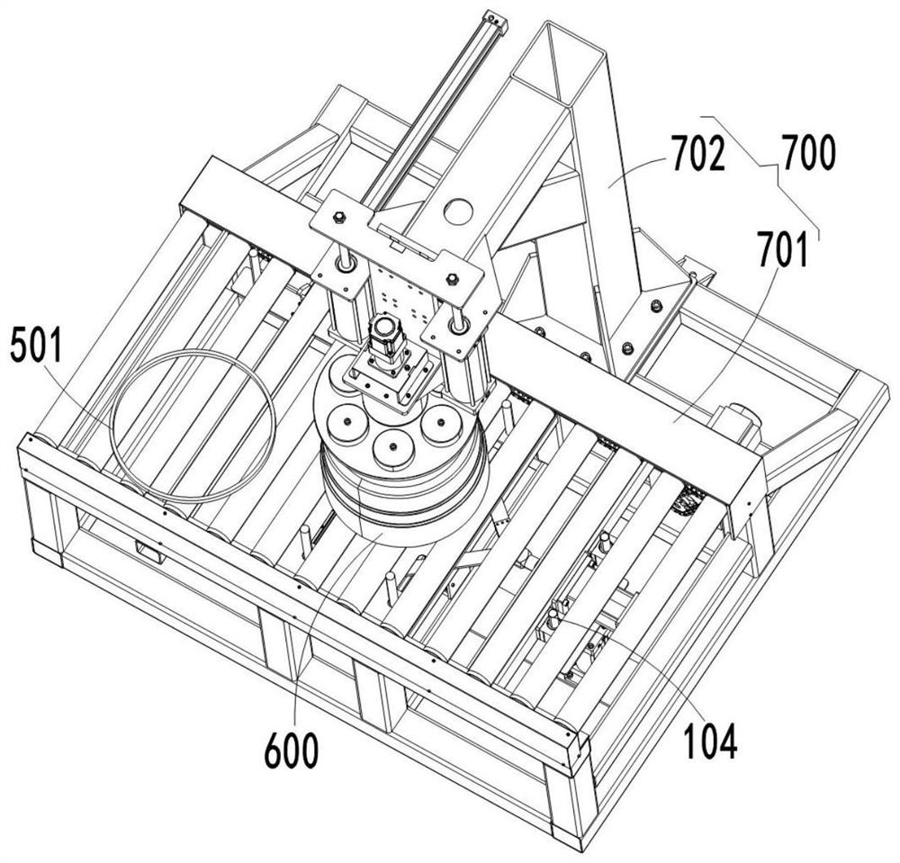
[0044] Such as Figure 1-Figure 9 As shown, a wheel hub and barrel-shaped workpiece edge cutting equipment includes a control unit and a delivery unit 100, a positioning unit 200, a clamping rotation unit 300 and a cutting unit 400 respectively connected to the control unit; the positioning unit 200 has a closed state and an open state. State, when the positioning unit 200 is in the closed state, the central axis of clamping the workpiece 600 to the workpiece 600 is coaxial with the rotation center of the clamping rotation unit 300, and when the positioning unit 200 is in the open state, a moving space 208 is formed in the positioning unit 200 The control unit is configured to control the cutting unit 400 to rise to the cutting position through the moving space 208 and perform cutting work when the positioning unit 200 is switched to the open state. The above-mentioned control unit can be PLC or industrial computer, etc., including electrical control, pneumatic control, contro...

Embodiment 2

[0055] The present invention also provides a method for processing the edge of the wheel hub and the barrel-shaped workpiece. The method for processing the edge of the wheel hub and the barrel-shaped workpiece includes the following steps:

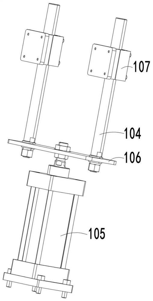
[0056] S1: the conveying unit 100 runs, the workpiece 600 to be processed is placed on the conveying unit 100, and the workpiece 600 is conveyed by the workpiece transfer side 101; the second driving device 105 drives the intercepting shaft 104 to rise and intercept the workpiece 600, and the current workpiece 600 is processed After the process is completed, the second driving device 105 drives the interception shaft 104 to drop to the initial position; the conveying unit 100 drives the workpiece 600 for a certain distance to the bottom of the clamping and rotating unit 300, and the conveying unit 100 stops;

[0057] S2: The third driving device 202 drives the positioning shaft 201 to move toward each other in the front and rear direction, ...


PUM


Abstract

The invention relates to the technical field of workpiece cutting, in particular to hub and barrel-shaped workpiece edge cutting equipment and a processing method. The cutting equipment comprises a control unit as well as a conveying unit, a positioning unit, a clamping rotating unit and a cutting unit, wherein the positioning unit is provided with a closed state and an open state; when the positioning unit is in the closed state, a workpiece is clamped until the center of the workpiece is coaxial with a rotation center of the clamping rotating unit; when the positioning unit is in the open state, a movable space is formed in the positioning unit; when the control unit is configured to ascend to the cutting position and cut the workpiece when the positioning unit is switched to the open state. The positioning unit in the embodiment of the invention is closed to clamp the workpiece, and is opened; the cutting unit ascends to the cutting position and is matched with the clamping rotating unit for directly cutting the workpiece, so that processing efficiency is not affected by processing margin, and processing efficiency is obviously improved; and cutting liquid is not used in a processing process, so that environmental pollution is not easily caused.

Description

technical field [0001] The invention relates to the technical field of workpiece cutting, in particular to a wheel hub and barrel-shaped workpiece edge cutting equipment and a processing method. Background technique [0002] At present, the edge of the wheel hub and barrel-shaped workpiece is generally removed by machining methods such as lathe or milling machine to remove the machining allowance. Processing by conventional machining has the following disadvantages: (1) The lathe or milling machine occupies a large area, and because the traditional processing methods such as turning or milling cut off the processed material layer by layer, the processing efficiency will be restricted by the size of the machining allowance Reduce processing efficiency; (2) Environmental pollution, traditional processing methods will process excess metal materials into debris, which is not easy to collect, and is not conducive to secondary recycling applications to cause environmental pollutio...

Claims


Application Information

Patent Timeline
Patent Type & Authority Applications(China)
IPC IPC(8): B23K37/00B23K37/02B23K37/047
CPCB23K37/00B23K37/0211B23K37/047B23K37/0247
Inventor 袁志勇彭伟超王立超
Owner 德州西恩数控设备股份有限公司
Why Eureka
Try Eureka