Novel photoacoustic spectrum gas sensor
A technology of gas sensor and photoacoustic spectroscopy, which is applied in instruments, scientific instruments, and material analysis through optical means, etc., can solve the problems of photoacoustic spectroscopy gas sensor with limited wavelength, limited detected gas, and limited manufacturing process, etc. To achieve the effects of diversity and selectivity, size reduction, and cost reduction
- Summary
- Abstract
- Description
- Claims
- Application Information
AI Technical Summary
Problems solved by technology
Method used
Image
Examples
Embodiment 1
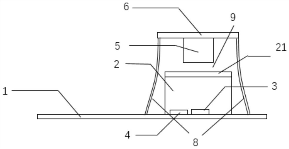
[0023] refer to figure 1 , a new type of photoacoustic spectrum gas sensor, including a main control board 1, a plurality of connecting brackets 8 are symmetrically installed on the main control board 1, a light source driving board 6 is installed on the upper ends of the plurality of connecting brackets 8, and the light source driving board 6 An electrically adjustable light source 5 is installed in the center of the lower surface. The electrically adjustable light source 5 is located on the central axis of a plurality of connecting brackets 8 .
[0024] The upper surface of the main control board 1 is located between a plurality of connecting brackets 8 and an air chamber cover 2 is installed. An air gap 9 is formed, and a photodetector 3 and a pickup 4 are respectively installed on the main control board 1. Modulate the light source 5 directly below.
[0025] The main control board 1 is equipped with a micro control unit MCU, which is used to control the light source driv...
Embodiment 2
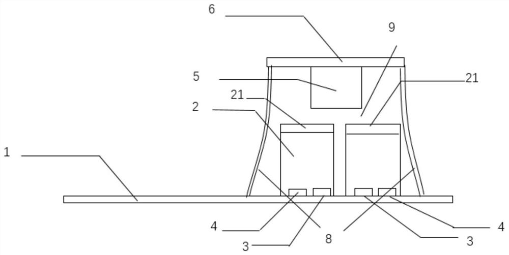
[0030] refer to figure 2 , a novel photoacoustic spectrum gas sensor, which is basically consistent with Embodiment 1, the difference is that:
[0031] The upper surface of the main control board 1 is located between a plurality of connecting brackets 8, and two air chamber covers 2 are symmetrically installed. The upper surface of each air chamber cover 2 is equipped with a light-transmitting window 21, and the two light-transmitting windows 21 An air gap 9 is formed between the electrically modulatable light source 5, and the main control board 1 is located in the two air chamber covers 2 respectively equipped with a photodetector 3 and a pickup 4, and the two photodetectors 3 are connected to the electrically modulatable light source 5 Symmetrical and all located directly below the electrically modulatable light source 5 .
[0032] When this embodiment is in use, when it is necessary to detect two gases at the same time, such as carbon dioxide and methane, a certain conce...
Embodiment 3
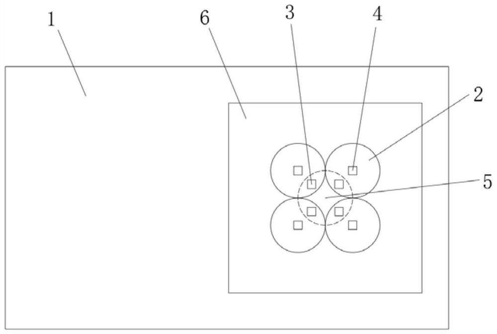
[0034] refer to image 3 , a novel photoacoustic spectrum gas sensor, which is basically consistent with Embodiment 1, the difference is that:
[0035] The upper surface of the main control board 1 is located between a plurality of connecting brackets 8, and a plurality of air chamber covers 2 are mounted symmetrically in a ring. The upper surface of each air chamber cover 2 is equipped with a light-transmitting window 21, and a plurality of light-transmitting windows An air gap 9 is formed between 21 and the electrically modulatable light source 5, and a photodetector 3 and a pickup 4 are installed on the main control board 1 in each air chamber cover 2, and a plurality of photodetectors 3 are connected to the electrically modulatable light source. 5 are circularly symmetrical, and each photodetector 3 is located at the coincidence of the vertical projection area of the electrically adjustable light source 5 on the main control board 1 and the vertical projection area of ...
PUM
 Abstract
Description
Claims
Application Information
 - R&D
- Intellectual Property
- Life Sciences
- Materials
- Tech Scout
- Unparalleled Data Quality
- Higher Quality Content
- 60% Fewer Hallucinations
Browse by: Latest US Patents, China's latest patents, Technical Efficacy Thesaurus, Application Domain, Technology Topic, Popular Technical Reports.
© 2025 PatSnap. All rights reserved.Legal|Privacy policy|Modern Slavery Act Transparency Statement|Sitemap|About US| Contact US: help@patsnap.com


