Centrifugal pump

A centrifugal pump and vane technology, applied in the field of centrifugal pumps and aerospace centrifugal pumps, can solve the problems of inability to adopt anti-cavitation measures of double suction impellers, reduce the pressure and flow characteristics of centrifugal pumps, and small volume of centrifugal pumps, and achieve the balance shaft. The effect of reducing the force, reducing the processing difficulty, and reducing the leakage of the tip clearance

Pending Publication Date: 2021-08-24
XIAN AERONAUTICAL UNIV
View PDF0 Cites 1 Cited by
  • Summary
  • Abstract
  • Description
  • Claims
  • Application Information

AI Technical Summary

Problems solved by technology

[0002] In order to reduce the volume and size of centrifugal pumps, aerospace systems are increasing the rotational speed, and the resulting problem is that the centrifugal pumps are small in size, resulting in the impeller running at a speed of tens of thousands or even tens of thousands of revolutions. There is a blade tip clearance in an open centrifugal pump; because the pressure on the pressure surface of the blade is higher than the pressure on the suction surface, this part of the liquid flow bypasses the edge of the blade top and enters the axial gap between the shell and the blade, and the A leakage flow is formed at the blade tip clearance, and finally returns to the impeller inlet so that a part of the liquid flow in the impeller always circulates in the clearance, resulting in energy loss. This flow is called clearance leakage flow, which causes hydraulic efficiency reduction and axial force problems; and When the impeller of the centrifugal pump rotates at high speed to do work on the aviation liquid, it is easy to generate cavitation in the low-pressure area, and the cavitation will reduce the pressure and flow characteristics of the centrifugal pump; there are many methods and structures for the centrifugal pump to prevent cavitation, such as double-suction impellers, additional Inducer and other measures, but the existing centrifugal pump structure needs to be changed; and for aerospace systems that have limited the size, installation interface position, quality, and processing cycle of the centrifugal pump, it is impossible to use double-suction impellers, add inducers, etc. Anti-cavitation measures need to design a new anti-cavitation centrifugal pump structure

Method used


Image

  • Centrifugal pump
  • Centrifugal pump
  • Centrifugal pump

Examples


Embodiment Construction

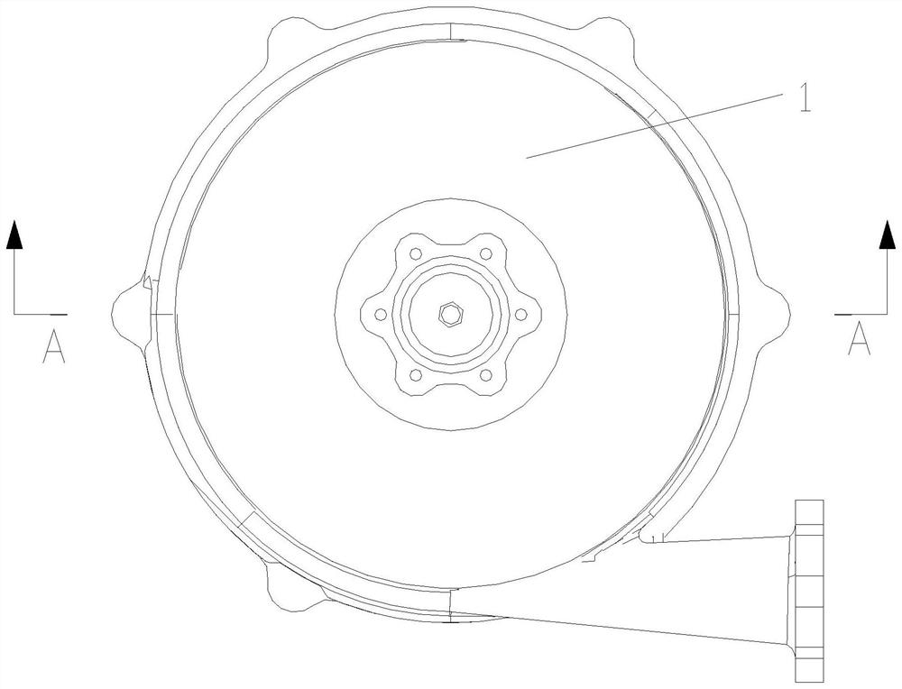
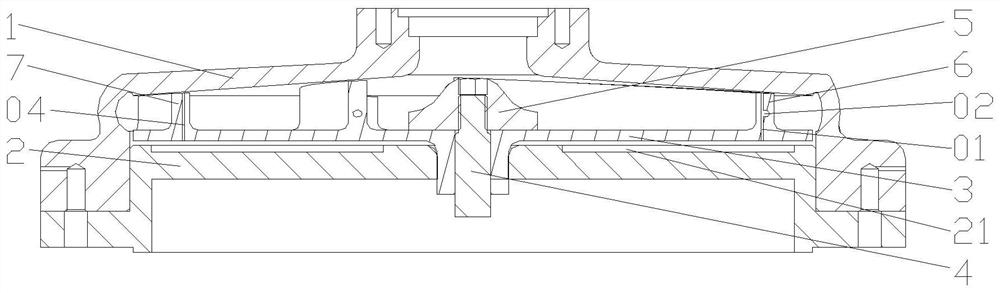
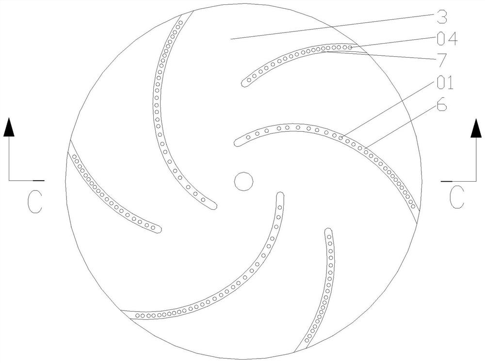
[0024] figure 1 It is a top view structure schematic diagram of the present invention; figure 2 for the invention figure 1 Schematic diagram of the structure in the A-A direction; image 3 It is a structural schematic diagram of the impeller of the present invention; Figure 4 for the invention image 3 Schematic diagram of the structure in the C-C direction; Figure 5 It is a side view structural schematic diagram of the present invention; Figure 6 for the invention Figure 5 Schematic diagram of the structure in the B-B direction; Figure 7 It is a schematic cross-sectional structural diagram of the present invention along the blade extension direction; as shown in the figure, the axial direction in this solution is based on the axial direction of the transmission shaft 4, and the radial direction is based on the radial direction of the transmission shaft 4. In this embodiment The centrifugal pump includes a volute 1, a back cover 2 and an impeller 3, and the impell...


PUM


Abstract

The invention discloses a centrifugal pump which comprises a volute, a rear cover plate and an impeller. The impeller is rotationally arranged between the volute and the rear cover plate, and blades are connected to the impeller; axial holes are formed in each blade, and the axial holes penetrate through the blades and the impeller; and the multiple axial holes are formed in the blades in the extending directions of the blades at intervals, and at least one of the following effects including reduction of liquid backflow in blade top gaps and reduction of cavitation and axial force can be achieved, so that the efficiency of the centrifugal pump is improved.

Description

technical field [0001] The invention relates to the field of aerospace centrifugal pumps, in particular to a centrifugal pump. Background technique [0002] In order to reduce the volume and size of centrifugal pumps, aerospace systems are increasing the rotational speed, and the resulting problem is that the centrifugal pumps are small in size, resulting in the impeller running at a speed of tens of thousands or even tens of thousands of revolutions. There is a blade tip clearance in an open centrifugal pump; because the pressure on the pressure surface of the blade is higher than the pressure on the suction surface, this part of the liquid flow bypasses the edge of the blade top and enters the axial gap between the shell and the blade, and the A leakage flow is formed at the blade tip clearance, and finally returns to the impeller inlet, so that a part of the liquid flow in the impeller always circulates in the clearance, causing energy loss. This flow is called clearance ...

Claims


Application Information

Patent Timeline
Patent Type & Authority Applications(China)
IPC IPC(8): F04D1/00F04D29/24F04D29/22F04D29/66
CPCF04D1/00F04D29/2266F04D29/2272F04D29/245F04D29/669
Inventor 晁文雄曹庆年郝杰吴奇段跟定范文雯何文博
Owner XIAN AERONAUTICAL UNIV
Why Eureka
Try Eureka