A drying machine for storage of agricultural products
A technology of mechanical equipment and agricultural products, applied in the field of drying machinery and equipment for agricultural product storage, can solve the problems of agricultural products not moving, sticking to each other, and unable to dry, and achieve the effects of accelerating dehydration, increasing storage time, and accelerating drying
- Summary
- Abstract
- Description
- Claims
- Application Information
AI Technical Summary
Problems solved by technology
Method used
Image

Examples
Embodiment 1
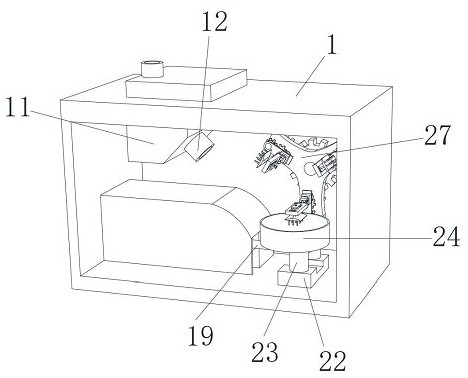
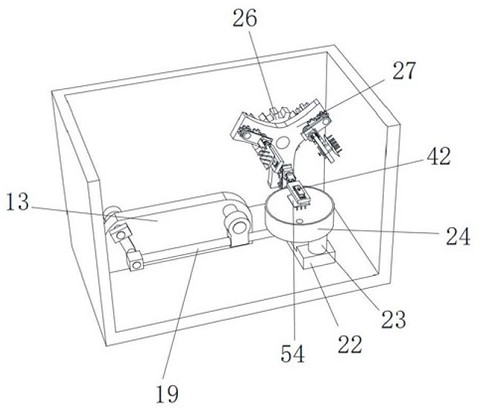
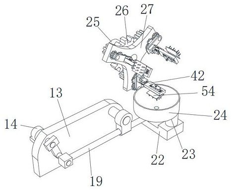
[0038] combine figure 1 , figure 2 , image 3 , Figure 4 , Image 6 and Figure 9 , a drying mechanical equipment for agricultural product storage, including a drying box 1, a dryer assembly 11 is fixedly installed in the drying box 1, an air outlet duct 12 is fixedly installed on the dryer assembly 11, and the drying box 1 is provided with The gear turning device, the shovel device and the shovel device, the shovel device is on the turning gear device, the shovel device is below the shovel device, the tooth turning device includes the motor two 25, and the main gear is fixedly installed on the output shaft of the motor two 25 26. A triangular plate 27 is fixedly installed on the output shaft of the motor two 25, the end of the triangular plate 27 is fixedly installed with a pinion two 3, the inner wall of the triangular plate 27 is horizontally rotated and installed with a rotating rod three 29, and the end of the rotating rod three 29 is fixed A pinion gear 1 28 is in...
Embodiment 2
[0041] On the basis of Example 1: combining figure 1 , figure 2 , image 3 , Figure 4 , Image 6 and Figure 8 The shovel device includes a rear insertion mechanism and a front insertion mechanism. The rear insertion mechanism includes a main bracket 38. The end of the main bracket 38 is fixedly installed with a rotating rod 34. The main bracket 38 is provided with a T-shaped chute 4. The T-shaped sliding The slot 4 is provided with two sockets one 39, the end of the main bracket 38 is fixedly installed with a plunger 44, and a C-shaped plunger 41 is horizontally slidably connected between the two sockets one 39, and the C-shaped plunger 41 and A miniature spring 43 is fixedly installed between the main brackets 38 , a rubber plate 45 is installed on the inner side wall of the insertion rod 44 , and a miniature spring 2 46 is fixedly installed between the rubber plate 45 and the insertion rod 44 .
[0042] In use, when the main bracket 38 drives the side bracket 5 to ro...
Embodiment 3
[0044] On the basis of Example 1: combining figure 1 , figure 2 , image 3 , Figure 4 , Image 6 and Figure 7 , the front insertion mechanism includes a side bracket 5, a cross insert plate 48 is fixedly installed on the side bracket 5, two insertion holes 49 are provided through the cross insert plate 48, and a slot 47 is opened at the end of the side bracket 5, and the side bracket The end of 5 is fixedly installed with an auxiliary bracket 42, the auxiliary bracket 42 is provided with a chute 51, the cross insert 48 is inserted into the T-shaped slot 4, the insertion rod 44 is inserted into the slot 47, and the C-shaped insert is inserted into the slot 47. The rod 41 is inserted between the two jacks 49 and the first jack 39, the rubber plate 45 is attached to the end of the side bracket 5, the auxiliary bracket 42 is installed with a connecting frame 52, and the connecting frame 52 is inserted in the chute 51. The second connecting rod 53 is fixedly installed at th...
PUM
 Abstract
Description
Claims
Application Information
 - R&D
- Intellectual Property
- Life Sciences
- Materials
- Tech Scout
- Unparalleled Data Quality
- Higher Quality Content
- 60% Fewer Hallucinations
Browse by: Latest US Patents, China's latest patents, Technical Efficacy Thesaurus, Application Domain, Technology Topic, Popular Technical Reports.
© 2025 PatSnap. All rights reserved.Legal|Privacy policy|Modern Slavery Act Transparency Statement|Sitemap|About US| Contact US: help@patsnap.com