
Preparation method of gate dielectric layer

A gate dielectric layer and dielectric layer technology, which is applied in the manufacture of circuits, electrical components, semiconductors/solid-state devices, etc., can solve the problems of high time cost and removal of residues, so as to improve yield rate, shorten preparation time, and improve device reliability properties as well as the effect of device performance on

Pending Publication Date: 2021-08-24
SHANGHAI HUALI INTEGRATED CIRCUTE MFG CO LTD
View PDF6 Cites 0 Cited by
  • Summary
  • Abstract
  • Description
  • Claims
  • Application Information

AI Technical Summary

Problems solved by technology

[0003] From the perspective of device reliability, an amorphous silicon capping layer is introduced into the gate structure. The amorphous silicon capping layer can be used as an oxygen absorbing layer to reduce the material defects of the high dielectric constant dielectric layer. However, after the deposition and annealing of the rear capping layer, Agglomeration of amorphous silicon occurs, and in the subsequent polysilicon removal process, due to the agglomeration of amorphous silicon, there is residue during removal;
[0004] In the existing technology, the Q-time control method is adopted to solve this problem, that is, the annealing of the rear capping layer can only be performed at least 6 hours after the formation of the amorphous silicon capping layer, and the time cost is relatively high.

Method used


Image

  • Preparation method of gate dielectric layer
  • Preparation method of gate dielectric layer
  • Preparation method of gate dielectric layer

Examples


specific Embodiment approach

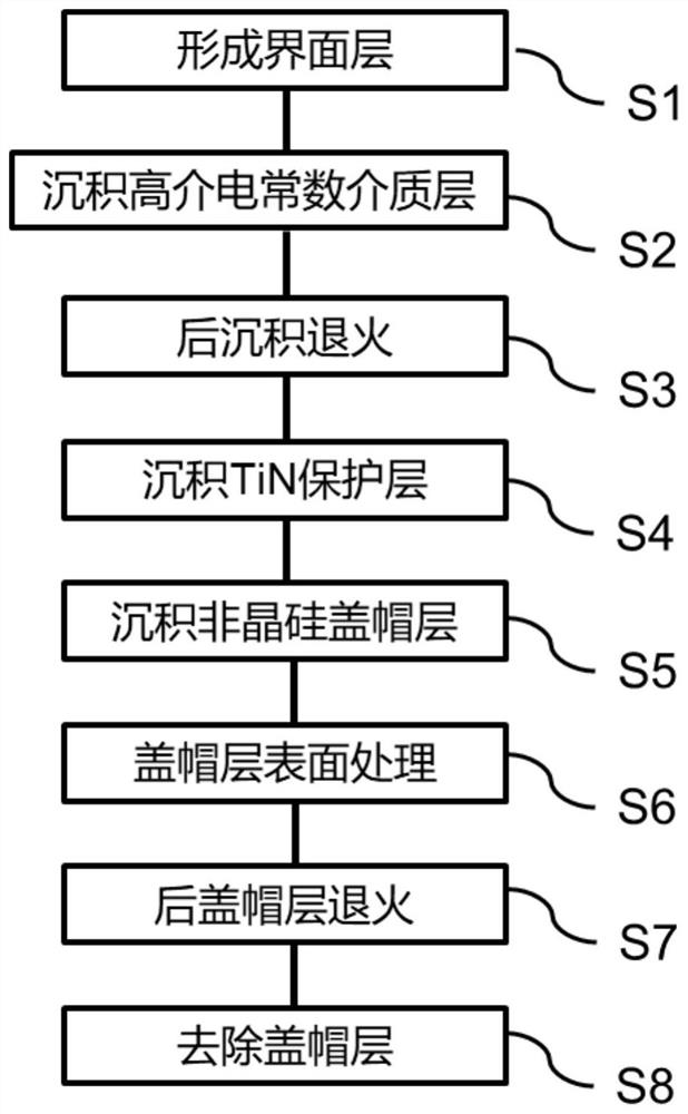
[0036] figure 1 It is a schematic diagram of the preparation method of the gate dielectric layer of the present invention, and the specific implementation method is as follows:

[0037] The method for preparing a gate dielectric layer in this embodiment includes:

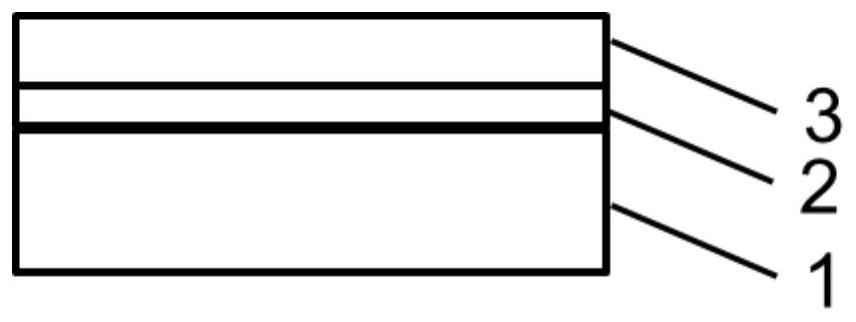
[0038] Step S1, such as figure 2 , provide a silicon substrate, form an ultra-thin interface layer 2 on the surface of the silicon substrate 1, the ultra-thin interface layer 2 is SiO 2 ; The interface layer is formed by means of wet ozone carrying or atomic oxygen thermal oxidation, the thickness of the interface layer is 6 to 10 angstroms, and the thickness of the interface layer in this embodiment is 8 angstroms.

[0039] Step S2, such as image 3 , to deposit a layer of high dielectric constant dielectric layer 3; the high dielectric constant dielectric layer 3 is deposited by atomic layer deposition, and the material of high dielectric constant dielectric layer 3 is HfO 2 , the thickness of the high dielec...


PUM

PropertyMeasurementUnit
thicknessaaaaaaaaaa
thicknessaaaaaaaaaa
thicknessaaaaaaaaaa

Abstract

The invention discloses a preparation method of a gate dielectric layer. The method comprises the following steps of S1, providing a silicon substrate, and forming an interface layer on the surface of the silicon substrate; S2, depositing a high dielectric constant dielectric layer; S3, carrying out post-deposition annealing; S4, depositing a TiN protective layer; S5, depositing an amorphous silicon cap layer; S6, treating the surface of the cap layer by adopting a plasma oxidation method; S7, annealing a rear cap layer; and S8, removing the cap layer. According to the method, the agglomeration of amorphous silicon can be avoided, residue of the cap layer in a polycrystalline silicon removal process can be avoided, and meanwhile, the preparation time is shortened.

Description

technical field [0001] The invention relates to a method for manufacturing a semiconductor integrated circuit, in particular to a method for preparing a gate dielectric layer. Background technique [0002] The size of semiconductor integrated circuit devices is continuously reduced according to Moore's law, and the thickness of the gate dielectric is continuously reduced, but the leakage current of the gate is also increased. In order to solve the problem of gate leakage, a high dielectric constant material is mainly used to replace the traditional SiO2 / SiON. At present, the challenge faced by the high dielectric constant dielectric layer is to maintain the high drive current and device reliability of the device. [0003] From the perspective of device reliability, an amorphous silicon capping layer is introduced into the gate structure. The amorphous silicon capping layer can be used as an oxygen absorbing layer to reduce the material defects of the high dielectric constan...

Claims


Application Information

Patent Timeline
Patent Type & Authority Applications(China)
IPC IPC(8): H01L21/28
CPCH01L21/28229
Inventor 姜兰
Owner SHANGHAI HUALI INTEGRATED CIRCUTE MFG CO LTD
Learn More