Infrared imaging lens and imaging equipment

An infrared imaging and lens technology, applied in the field of imaging lenses, can solve the problems of small clear aperture, large temperature drift, small field of view, etc., and achieve the effect of compensating for focus shift, high-definition imaging performance, and high-definition resolution.

Active Publication Date: 2021-08-27
JIANGXI LIANCHUANG ELECTRONICS CO LTD
View PDF5 Cites 1 Cited by
  • Summary
  • Abstract
  • Description
  • Claims
  • Application Information

AI Technical Summary

Problems solved by technology

However, most infrared imaging lenses on the market have shortcomings such as large temperatur

Method used


Image

  • Infrared imaging lens and imaging equipment
  • Infrared imaging lens and imaging equipment
  • Infrared imaging lens and imaging equipment

Examples


no. 1 example

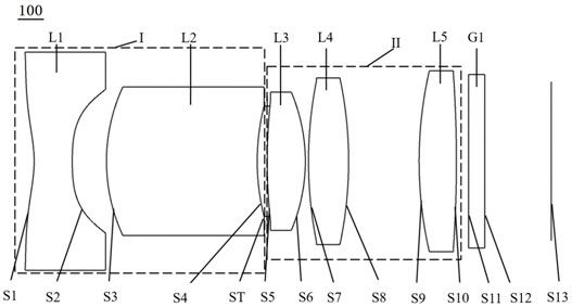
[0072] see figure 1 , which is a schematic structural view of the infrared imaging lens 100 provided in the first embodiment of the present invention, the infrared imaging lens 100 sequentially includes a first group I with a negative focal power, a light Stop ST, second group II with positive power, and filter G1.

[0073] The first group I comprises in turn from the object side to the imaging surface: a first lens L1 with negative refractive power, the object side S1 of the first lens is concave at the paraxial place, and the image side S2 of the first lens is concave; The second lens L2 with positive refractive power, the object side S3 of the second lens is a convex surface, and the image side S4 of the second lens is a concave surface;

[0074] The diaphragm ST is disposed between the second lens L2 and the third lens L3;

[0075] The second group II includes in order from the object side to the imaging surface: a third lens L3 with positive refractive power, the object...

no. 2 example

[0088] see Figure 5 , shows the structural diagram of the infrared imaging lens 200 provided in the second embodiment of the present invention, the structure of the infrared imaging lens 200 in this embodiment is roughly the same as that of the infrared imaging lens 100 in the first embodiment, the difference is that The curvature radius, thickness, and material selection of each lens of the optical imaging lens in this embodiment are different, and specific relevant parameters of each lens are shown in Table 3.

[0089] table 3

[0090]

[0091] The aspherical parameters of the infrared imaging lens 200 in this embodiment are shown in Table 4.

[0092] Table 4

[0093]

[0094] In this embodiment, the field curvature curve, the relative illuminance curve and the MTF curve in the working band of the infrared imaging lens 200 are respectively as follows Image 6 , Figure 7 and Figure 8 shown.

[0095] Depend on Image 6 It can be seen that the field curvature of...

no. 3 example

[0099] see Figure 9 , shows the structural diagram of the infrared imaging lens 300 provided in the third embodiment of the present invention, the structure of the infrared imaging lens 300 in this embodiment is roughly the same as that of the infrared imaging lens 100 in the first embodiment, the difference is that In this embodiment, the image side S10 of the fifth lens of the infrared imaging lens 300 is a concave surface, and the curvature radius, thickness, and material selection of each lens are also different. The relevant parameters of each lens are shown in Table 5.

[0100] table 5

[0101]

[0102] The aspherical parameters of the infrared imaging lens 300 in this embodiment are shown in Table 6.

[0103] Table 6

[0104]

[0105] In this embodiment, the field curvature curve, the relative illuminance curve and the MTF curve in the working band of the infrared imaging lens 300 are as follows Figure 10 , Figure 11 and Figure 12 shown.

[0106] Depend ...


PUM

PropertyMeasurementUnit
Optical lengthaaaaaaaaaa

Abstract

The invention discloses an infrared imaging lens and imaging equipment. The infrared imaging lens sequentially comprises a first group with negative focal power, a diaphragm and a second group with positive focal power from an object side to an imaging surface along an optical axis. The first group sequentially comprises a first lens with negative focal power and a second lens with positive focal power from the object side to the imaging surface, wherein the object side surface of the first lens is a concave surface in a paraxial position, and the image side surface of the first lens is a concave surface; the object side surface of the second lens is a convex surface, and the image side surface of the second lens is a concave surface. The second group sequentially comprises a third lens with positive focal power, a fourth lens with positive focal power and a fifth lens with positive focal power from the object side to the imaging surface, wherein the object side surface and the image side surface of the third lens are convex surfaces; the object side surface and the image side surface of the fourth lens are convex surfaces; and the object side surface of the fifth lens is a convex surface. The infrared imaging lens has the advantages of being large in clear aperture, large in field angle and stable in optical performance at the temperature ranging from -40 DEG C to 105 DEG C.

Description

technical field [0001] The invention relates to the technical field of imaging lenses, in particular to an infrared imaging lens and imaging equipment. Background technique [0002] The Driver Monitor System (DMS) can effectively regulate the driver's driving behavior, reduce accidents caused by human errors, and protect driving safety. In recent years, with the strengthening of car driving safety awareness and the continuous improvement of DMS-related laws and regulations at home and abroad, the number of cars equipped with DMS cameras has increased rapidly. At the same time, ToF (Time-of-Flight) lenses, which are widely used in mobile phones, use infrared light to measure distance and depth data for imaging, and have unique advantages in depth measurement, face recognition, motion capture, etc. , is an accurate and safe identification mode, which is very suitable for application in DMS. [0003] With the deep integration of ToF technology and DMS technology, ToF lenses u...

Claims


Application Information

Patent Timeline
IPC IPC(8): G02B13/00G02B13/06G02B13/14G02B13/18G02B7/02
CPCG02B7/028G02B13/0045G02B13/06G02B13/14G02B13/18
Inventor 梁流峰鲍宇旻曾吉勇
Owner JIANGXI LIANCHUANG ELECTRONICS CO LTD
Why Eureka
Try Eureka