Reflective eyepiece optical system and head-mounted near-eye display device

An optical system and reflective technology, applied in the optical field, can solve the problems of heavy optical structure, insufficient field of view, low image quality, etc., and achieve the effect of reducing cost and weight, improving optical indicators, and improving possibility

Active Publication Date: 2022-08-02
SHENZHEN NED OPTICS CO LTD
View PDF13 Cites 0 Cited by
  • Summary
  • Abstract
  • Description
  • Claims
  • Application Information

AI Technical Summary

Problems solved by technology

[0007] The technical problem to be solved by the present invention is that the existing optical structure is heavy, the image quality is not high, there is distortion, the viewing angle is not large enough, and mass production is difficult. Eyepiece optical system and head-mounted near-eye display device

Method used


Image

  • Reflective eyepiece optical system and head-mounted near-eye display device
  • Reflective eyepiece optical system and head-mounted near-eye display device
  • Reflective eyepiece optical system and head-mounted near-eye display device

Examples


no. 1 example

[0128] The eyepiece design data of the first embodiment are shown in Table 1 below:

[0129] Table I

[0130]

[0131]

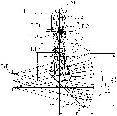
[0132] attached figure 1 It is the optical path diagram of the eyepiece optical system of the first embodiment, including: a first optical element L1 and a second optical element T2 arranged in sequence along the incident direction of the optical axis of the human eye, and a first lens group T1 located on the optical axis of the micro-image display IMG The first optical element L1 is used to transmit and reflect the image light from the micro-image display IMG; the second optical element T2 comprises an optical reflection surface L2, and the optical reflection surface L2 is concave to the viewing direction of the human eye; the first optical element L1 The image light refracted by the first lens group T1 is reflected to the second optical element T2, and then the image light reflected by the second optical element T2 is transmitted to the human eye EYE....

no. 2 example

[0136] The eyepiece design data of the second embodiment are shown in Table 2 below:

[0137] Table II

[0138]

[0139] attached Figure 5 It is the optical path diagram of the eyepiece optical system of the second embodiment, including: a first optical element L1 and a second optical element T2 arranged in sequence along the incident direction of the optical axis of the human eye, and a first lens group T1 located on the optical axis of the micro-image display IMG The first optical element L1 is used to transmit and reflect the image light from the micro-image display IMG; the second optical element T2 comprises an optical reflection surface L2, and the optical reflection surface L2 is concave to the viewing direction of the human eye; the first optical element L1 The image light refracted by the first lens group T1 is reflected to the second optical element T2, and then the image light reflected by the second optical element T2 is transmitted to the human eye EYE.

[0...

no. 3 example

[0143] The eyepiece design data of the third embodiment are shown in Table 3 below:

[0144] Table 3

[0145]

[0146] attached Figure 9 It is the optical path diagram of the eyepiece optical system of the third embodiment, including: a first optical element L1 and a second optical element T2 arranged in sequence along the incident direction of the optical axis of the human eye, and a first lens group T1 located on the optical axis of the micro-image display IMG The first optical element L1 is used to transmit and reflect the image light from the micro-image display IMG; the second optical element T2 comprises an optical reflection surface L2, and the optical reflection surface L2 is concave to the viewing direction of the human eye; the first optical element L1 The image light refracted by the first lens group T1 is reflected to the second optical element T2, and then the image light reflected by the second optical element T2 is transmitted to the human eye EYE.

[0147...


PUM


Abstract

The invention relates to a reflective eyepiece optical system and a head-mounted near-eye display device. The system comprises: a first optical element and a second optical element arranged in sequence along the incident direction of the optical axis of the human eye; a lens group; the first optical element is used to transmit and reflect the image light from the micro image display; the second optical element includes an optical reflection surface; the first optical element reflects the image light refracted by the first lens group to the second optical element On the optical element, the image light reflected by the second optical element is transmitted to the human eye; the first lens group includes a first sub-lens group and a second sub-lens group; the first sub-lens group and the second sub-lens group The effective focal length is a combination of positive and negative; the optical path is effectively folded, which reduces the overall size of the optical system and greatly eliminates aberrations. A highly immersive visual experience.

Description

technical field [0001] The present invention relates to the field of optical technology, and more particularly, to a reflective eyepiece optical system and a head-mounted near-eye display device. Background technique [0002] With the continuous development of ultra-miniaturization of electronic devices, head-mounted display devices and products are constantly emerging in military, industrial, medical, education, consumer and other fields. In a typical wearable computing system architecture, head-mounted display devices are key component. The head-mounted display device guides the video image light emitted by the miniature image display (such as transmissive or reflective liquid crystal display, organic electroluminescent device, DMD device) to the user's pupil through optical technology, and the user's near vision The scope realizes virtual and enlarged images, and provides users with intuitive and visible images, videos, and text information. The eyepiece optical system ...

Claims


Application Information

Patent Timeline
Patent Type & Authority Patents(China)
IPC IPC(8): G02B25/00G02B27/01
CPCG02B25/001G02B27/0172G02B2027/0178G02B27/0025G02B27/0176
Inventor 彭华军曹鸿鹏郭健飞
Owner SHENZHEN NED OPTICS CO LTD
Why Eureka
Try Eureka