Waste gas condensation recovery system using condensing unit and environment-friendly treatment method
A technology of condensation recovery and condensation unit, which is applied in chemical instruments and methods, separation methods, and dispersed particle separation, etc., and can solve problems such as inability to separate harmful gases
- Summary
- Abstract
- Description
- Claims
- Application Information
AI Technical Summary
Problems solved by technology
Method used
Image

Examples
Embodiment 1
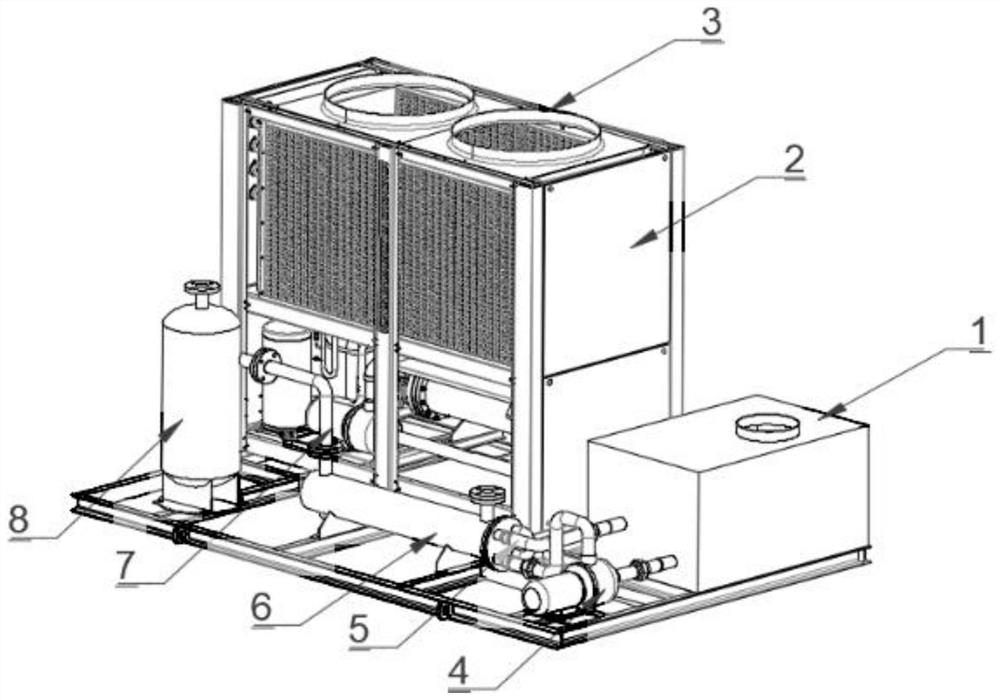
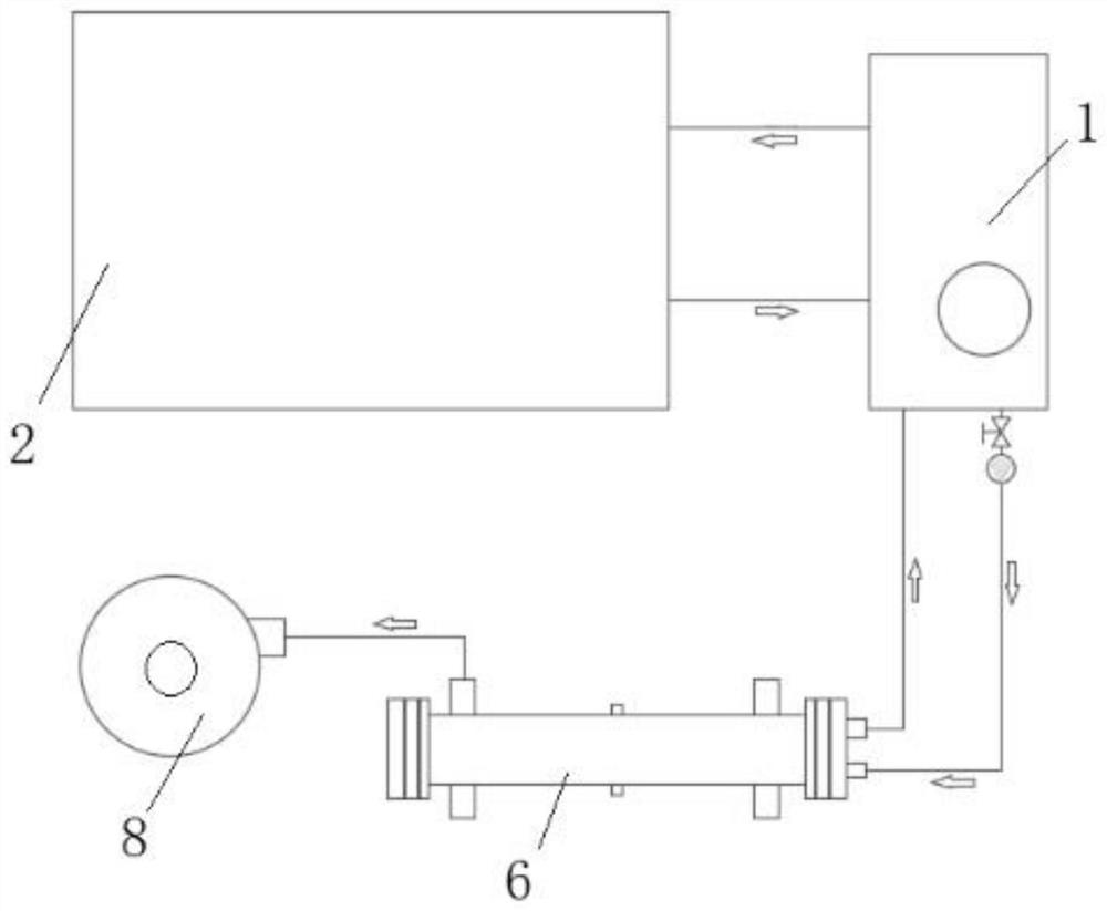
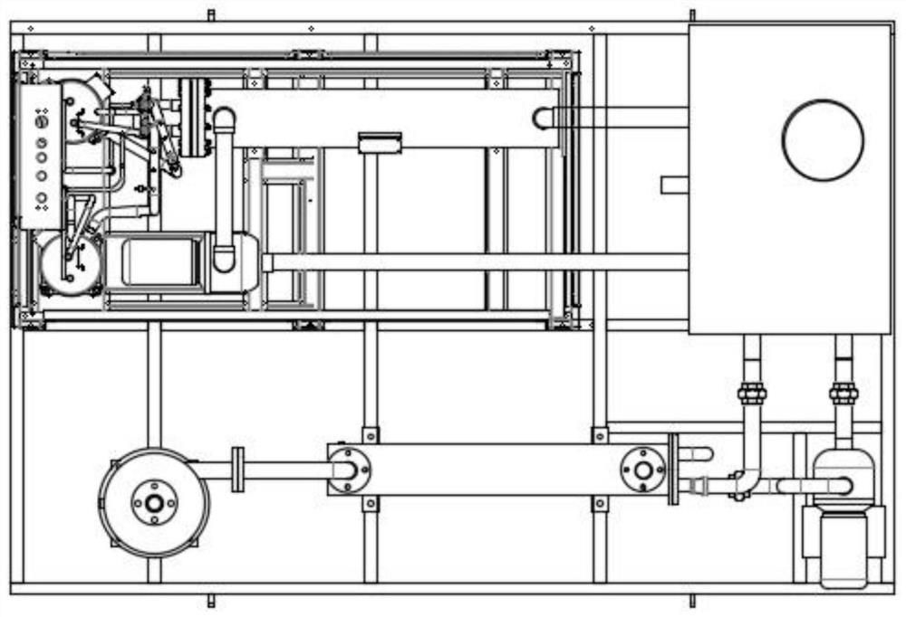
[0031] Example 1: Combining figure 1 and figure 2 and image 3 , Figure 4 Utilize the waste gas condensation recovery system of condensing unit, it is characterized in that, recovery system comprises refrigerating unit 2, and the cold air that refrigerating unit 2 comes out can carry out heat exchange with water in circulating water tank 1; The chilled water inlet pipe, the chilled water outlet pipe and the chilled water inlet pipe lead into the water-air heat exchanger 6, and the water-air heat exchanger 6 protrudes from the pipeline to connect the gas-liquid separator 8; the chilled water outlet pipe and the chilled water inlet pipe connect Entering into the water-air heat exchanger 6 enables the frozen water to cool down the water-air heat exchanger 6 and allow as much organic matter as possible to dissolve in the water during the process. The substantive technical effects played by the technical solution here and its realization process are as follows: the environment...
Embodiment 2
[0032] Embodiment 2: As a further improved solution or a side-by-side solution or an optional independent solution, the pipeline connecting the gas-liquid separator 8 and the water-gas heat exchanger 6 is the inlet pipe 7 .
Embodiment 3
[0033] Embodiment 3: As a further improved scheme or a side-by-side scheme or an optional independent scheme, the water-gas heat exchanger 6 includes an inlet pipeline for entering hot oil and gas containing water; the water-gas heat exchanger 6 also includes a water inlet and Outlet. The substantive technical effect and the realization process of the technical solution here are as follows: the water inlet and the water outlet can enter water, and can absorb hot oil and gas containing water.
PUM
 Abstract
Description
Claims
Application Information