Immersed liquid cooling sintering porous capillary core coupling micro-channel heat dissipation device

A technology of heat dissipation device and capillary core, which is applied in indirect heat exchangers, lighting and heating equipment, electrical components, etc., can solve the problem of poor phase change heat transfer capacity, low stability of working state, increased gas overflow resistance and boiling nucleation. problems such as the number of sites, to achieve the effect of high liquid density, enhanced heat transfer capacity and temperature uniformity, and prevention of local hot spots

Active Publication Date: 2021-09-07
XI AN JIAOTONG UNIV
View PDF9 Cites 6 Cited by
  • Summary
  • Abstract
  • Description
  • Claims
  • Application Information

AI Technical Summary

Problems solved by technology

[0003] The purpose of the present invention is to provide a submerged liquid-cooled sintered porous capillary core coupled micro-channel cooling device to overcome the existing ubiquitous problems such as poor phase change heat transfer capability and low working state stability. The sintering and bonding of the porous capillary core and the microchannel ensures the relative separation of the phase change gas-liquid channel in the heat dissipation structure at a small size. Significantly improve the phase change heat capacity and working stability of the device under medium and high heat flow

Method used


Image

  • Immersed liquid cooling sintering porous capillary core coupling micro-channel heat dissipation device
  • Immersed liquid cooling sintering porous capillary core coupling micro-channel heat dissipation device
  • Immersed liquid cooling sintering porous capillary core coupling micro-channel heat dissipation device

Examples


Embodiment Construction

[0034] Embodiments of the present invention are described in further detail below:

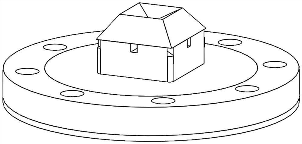
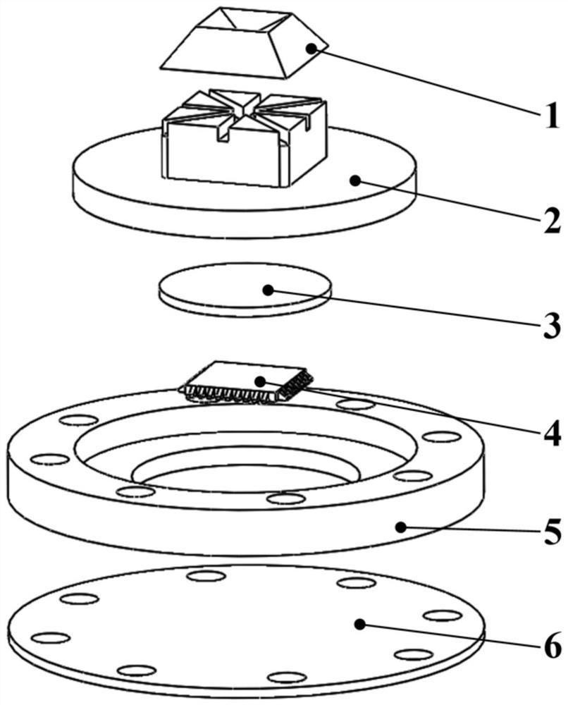
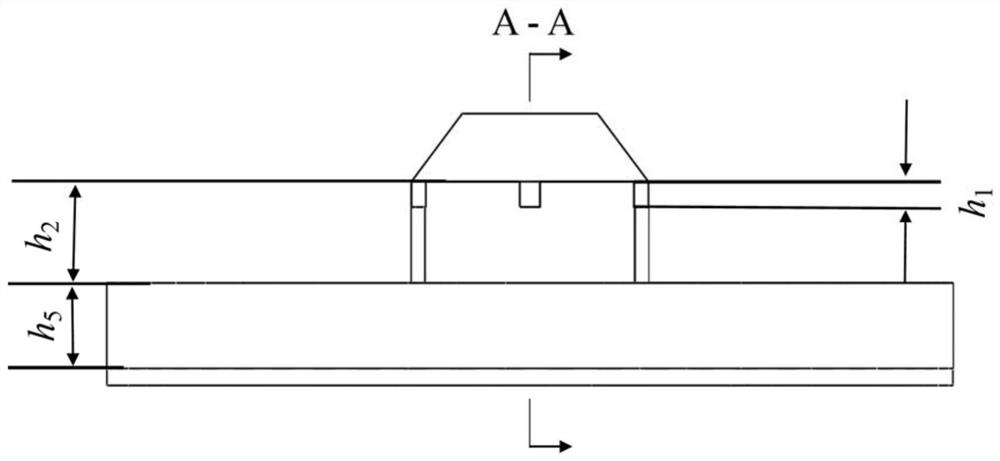
[0035] A submerged liquid-cooled sintered porous capillary core coupled microchannel heat sink, such as figure 1 , 2As shown, it includes a boiling-evaporation sintered porous capillary core 1 , an exhaust microchannel copper substrate 2 , a heat conducting sheet 3 , a chip heat source 4 , an insulating silica gel pad 5 , and a packaging substrate 6 . The boiling-evaporating sintered porous capillary core 1 is in the shape of a truncated prism, with a porous capillary core conical groove 9 on its top, and its bottom is in contact with the top surface of the polished exhaust microchannel copper substrate 2 and sintered into one. An exhaust microchannel 7 is line-cut above the exhaust microchannel copper substrate 2 . The lower half of the exhaust microchannel copper substrate 2 is a cylindrical soaking table, a heat conduction sheet 3 is attached to the bottom of the soaking table, and a chip...


PUM

PropertyMeasurementUnit
lengthaaaaaaaaaa
lengthaaaaaaaaaa
widthaaaaaaaaaa

Abstract

The invention discloses an immersed liquid cooling sintering porous capillary core coupling micro-channel heat dissipation device. An exhaust micro-channel copper substrate comprises a square boss and a circular soaking table, the boss is located at the center position of the upper side of the soaking table, a *-shaped exhaust micro-channel is formed in the boss through linear cutting, and a boiling-evaporation sintering porous capillary core is in the shape of a prismatic table. The top of the boiling-evaporation sintering porous capillary core is provided with a porous capillary core conical groove, the bottom of the boiling-evaporation sintering porous capillary core and the top face of the polished exhaust micro-channel copper substrate are in contact with each other and are sintered into a whole, a heat conduction piece adheres to the bottom of the soaking table, and a chip heat source adheres to the bottom of the heat conduction piece. The chip heat source is embedded on a packaging substrate, and a heat insulation silica gel pad capable of nesting the heat conduction piece and the chip heat source between the soaking table and the packaging substrate is tightly attached to the packaging substrate. According to the immersed liquid cooling sintering porous capillary core coupling micro-channel heat dissipation device, the phase-change heat transfer capacity and the working stability of the device under medium-high heat flow can be remarkably improved.

Description

technical field [0001] The invention relates to the field of phase change heat transfer enhanced by a sintered structure in a tiny space in micron heat transfer, in particular to a submerged liquid-cooled sintered porous capillary core coupled microchannel cooling device. Background technique [0002] With the rapid development of the microelectronics information industry, miniaturized and integrated electronic device clusters have higher and higher requirements for heat dissipation. Efficient and uniform release of heat generated by microelectronics in a short period of time has always been a challenge in the integrated circuit industry. major problem of development. Boiling heat transfer is a violent vaporization process that converts the working fluid from liquid to vapor through the generation, growth and detachment of a large number of bubbles. It has the advantages of high heat transfer efficiency and strong stability, and is considered to be the most promising solutio...

Claims


Application Information

Patent Timeline
Patent Type & Authority Applications(China)
IPC IPC(8): F28D15/04H01L23/427
CPCF28D15/046F28D15/0275H01L23/427
Inventor 张永海刘万渤朱志强杨小平魏进家
Owner XI AN JIAOTONG UNIV
Why Eureka
Try Eureka