Solution uniformity evaluation device and method
An evaluation device and evaluation method technology, applied in the field of instrument analysis, can solve the problems of inability to quantitatively determine the same sample solution, inaccurate determination of uniformity, etc.
- Summary
- Abstract
- Description
- Claims
- Application Information
AI Technical Summary
Problems solved by technology
Method used
Image
Examples
Embodiment 1
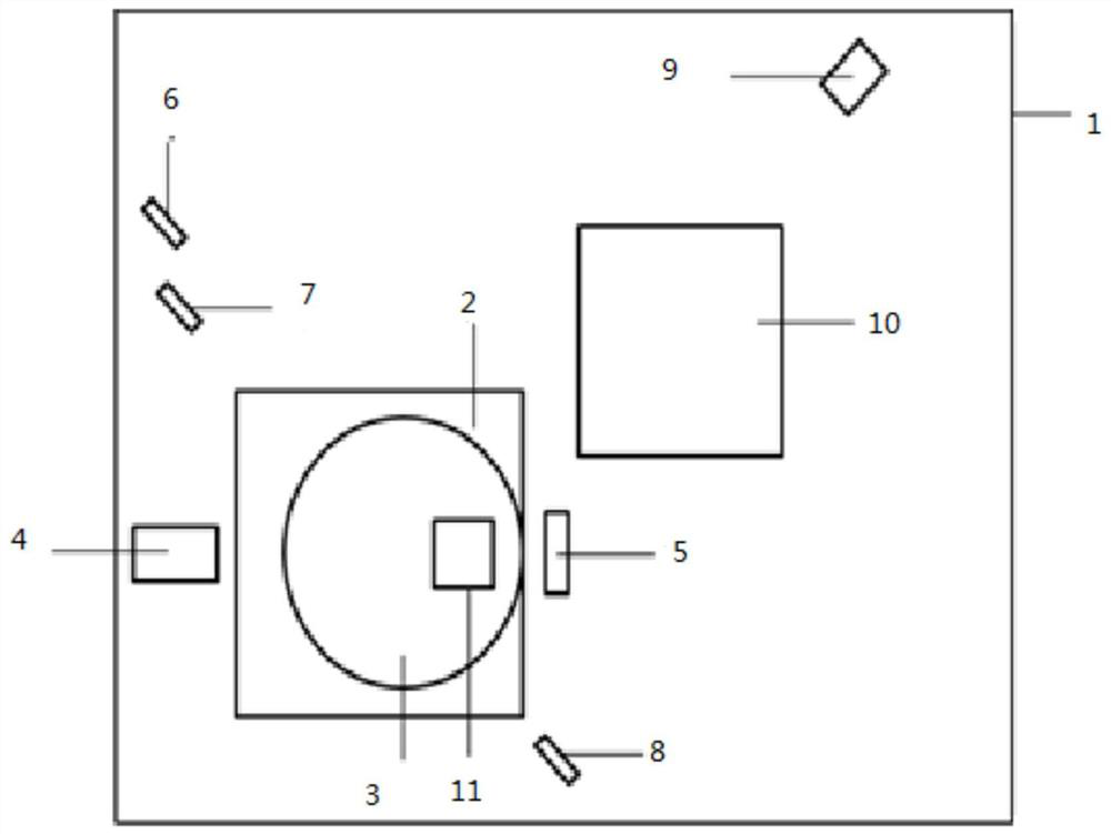
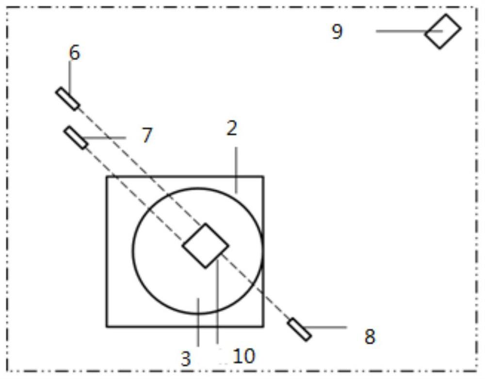
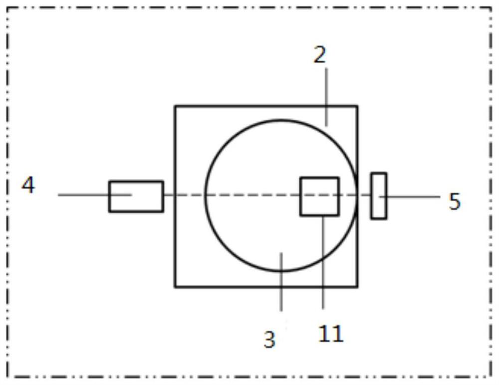
[0044] A solution uniformity evaluation device, comprising a box body 1, the box body 1 is an opaque structure, a black box body 1 can be used, and the box body 1 is provided with a cover, which can be opened and closed, and is used for placing and taking out the colorimetric A cuvette 11, a cuvette 11, a displacement part, a visible light emitting part, an imaging part, and a display part are built in the box body 1.
[0045] The work of the displacement unit, the visible light emission unit, the shooting unit and the display unit can all be controlled by an external control system. The control system is composed of a hardware part and a software part. The hardware part can use a computer or other types of controllers, and the software part is Program, the program is built into the hardware part, such as installing the operating software on the computer, and entering the control system interface of the operating software to control the displacement part, visible light emitting p...
Embodiment 2
[0054] A solution uniformity evaluation device, this embodiment is an improvement on the basis of embodiment 1.
[0055] On the basis of Embodiment 1, an ultraviolet light emitting part, a signal conversion part, and a data acquisition part are also provided in the cabinet 1, and the ultraviolet light emitting part, the signal conversion part, and the data acquisition part can control the corresponding work through the control system, Computer or other types of controllers can be used, such as installing operating software on the computer, controlled by a pre-set control program, and the ultraviolet light emitting part and data acquisition part can use communication connection, interface connection or data line according to the actual situation The way of connection is to establish a connection relationship with the computer, and the signal conversion part and the data acquisition part are connected by means of data line connection or communication connection.
[0056] The ult...
Embodiment 3
[0061] A method for evaluating the uniformity of a solution is carried out based on the evaluation devices of Examples 1 and 2.
[0062] Include the following steps:
[0063] Step 1, qualitative determination of solution uniformity: place the cuvette 11 containing the solution to be tested on the displacement part of the light-tight box 1, and the displacement part drives the cuvette 11 to move to the visible light emitted by the visible light emitting part. In the first optical path, the visible light emitting part emits visible light to the cuvette 11, and the photographing part vertically shoots the light and shadow picture formed by the visible light passing through the solution in the cuvette 11, and transmits the acquired picture signal to the display part, and the display part displays the picture of the light source, According to the picture of the light source, it is determined whether the Tyndall phenomenon occurs when the visible light passes through the solution in...
PUM
 Abstract
Description
Claims
Application Information
 - R&D
- Intellectual Property
- Life Sciences
- Materials
- Tech Scout
- Unparalleled Data Quality
- Higher Quality Content
- 60% Fewer Hallucinations
Browse by: Latest US Patents, China's latest patents, Technical Efficacy Thesaurus, Application Domain, Technology Topic, Popular Technical Reports.
© 2025 PatSnap. All rights reserved.Legal|Privacy policy|Modern Slavery Act Transparency Statement|Sitemap|About US| Contact US: help@patsnap.com


