Multipath effect suppression method for airborne imaging radar array antenna

A multipath effect and array antenna technology, which is suitable for antennas on movable objects, special data processing applications, radiation unit covers, etc., can solve the problem of relying on the digital signal processing capabilities of the back-end platform and cannot effectively suppress multipath effect, difficulty in completely separating clutter signals, etc.

Active Publication Date: 2021-09-07
AEROSPACE INFORMATION RES INST CAS
View PDF3 Cites 2 Cited by
  • Summary
  • Abstract
  • Description
  • Claims
  • Application Information

AI Technical Summary

Problems solved by technology

However, this method needs to process multipath information by establishing a database, which depends on the digital signal processing capability of the back-end platform
Moreover, it is difficult to completely separate the clutter signals by separating and suppressing the clutter generated by the multipath effect to extract useful signals, and the multipath effect cannot be effectively suppressed

Method used


Image

  • Multipath effect suppression method for airborne imaging radar array antenna
  • Multipath effect suppression method for airborne imaging radar array antenna
  • Multipath effect suppression method for airborne imaging radar array antenna

Examples


Embodiment

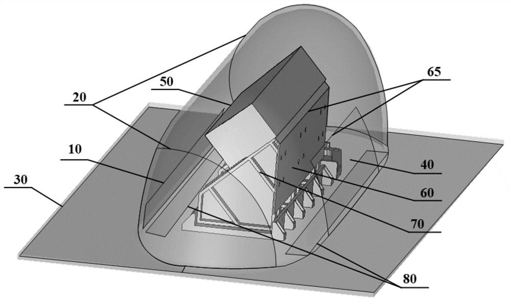
[0063] Step (1): Determine the electromagnetic wave reflection area where the airborne complex configuration affects the antenna phase pattern.

[0064] refer to figure 1 , to determine all reflection areas of the airborne complex configuration, including: radome back arc section 10, radome inner rectifying section 20, radome straight section 30, radome front 40, antenna back 50, bracket front 60, radome Three quarters of the front and one quarter of the bracket are 65, the back and sides of the bracket are 70, and the two sides of the aircraft truss are 80.

[0065] Step (2): Complete full-wave electromagnetic simulation modeling

[0066] A full-wave electromagnetic simulation model is established according to the truss structure parameters under the belly, the electromagnetic characteristic parameters of the radome and the radiation performance parameters of the array antenna.

[0067] Step (3): Obtain the radiation pattern of the single antenna of the imaging radar array ...


PUM


Abstract

The invention provides a multipath effect suppression method for an airborne imaging radar array antenna, and the method is simple and convenient to operate, can greatly suppress the influence of the multipath effect on the flatness of a directional diagram, and can well improve the imaging and distance measurement precision of an antenna on an airplane. According to the multipath effect suppression method for the airborne complex-configuration imaging radar array antenna provided by the invention, a wave-absorbing material attaching scheme is finally formed, and the wave-absorbing material attaching position is located on the inner side of the antenna housing and the surrounding space of the array antenna, under the condition that the signal transmission characteristic and the aerodynamic property in the flight process of an aircraft are not influenced, the multi-path effect is restrained, the material cost is reduced, implementation is easy and convenient, and the installation strength is reduced.

Description

technical field [0001] The invention belongs to the technical field of radar antennas, and in particular relates to a multipath effect suppression method for an airborne imaging radar array antenna. Background technique [0002] The high-resolution earth observation system will build an advanced earth observation system with high-precision observation capabilities, high spatial resolution, high spectral resolution, and high temporal resolution, forming a global coverage, all-time, all-weather earth observation capability . As an important part of the high-resolution earth observation system, the high-resolution 3D imaging radar based on the airborne platform plays an irreplaceable role. The array antenna of imaging radar is generally installed in the truss and radome assembly under the belly of the carrier aircraft. The truss structure, radome, array antenna and other complex configurations, electromagnetic waves will produce multipath effects in the above-mentioned complex...

Claims


Application Information

Patent Timeline
Patent Type & Authority Applications(China)
IPC IPC(8): G06F30/23H01Q1/28H01Q1/42
CPCG06F30/23H01Q1/28H01Q1/42
Inventor 潘洁朱金彪丁赤飚吴一戎
Owner AEROSPACE INFORMATION RES INST CAS
Why Eureka
Try Eureka