Automatic robot welding auxiliary tool

A technology of robot welding and auxiliary tooling, which is applied in the direction of welding/cutting auxiliary equipment, auxiliary devices, welding equipment, etc., and can solve the problems of increasing cost expenditure, time-consuming and laborious, etc.

Inactive Publication Date: 2021-09-10
NANJING YUQUN COMM TECH CO LTD
View PDF0 Cites 1 Cited by
  • Summary
  • Abstract
  • Description
  • Claims
  • Application Information

AI Technical Summary

Problems solved by technology

[0004] The purpose of the present invention is to solve the problem that when replacing tubular parts with different welding diameters, it is necessary to make an auxiliary tooling, which is time-consuming and laborious, and also increases the cost.

Method used


Image

  • Automatic robot welding auxiliary tool
  • Automatic robot welding auxiliary tool
  • Automatic robot welding auxiliary tool

Examples


Embodiment 1

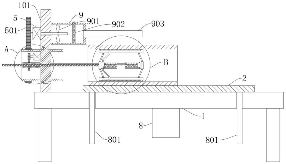
[0030] refer to Figure 1-6 , an automatic robot welding auxiliary tool, including a workbench 1, also includes: a mounting frame 101, fixedly connected to the workbench 1; a cylinder 4, connected to the mounting frame 101; a sliding rod 6, one end of which is fixedly connected to the cylinder 4 top; the first slider 601, sliding on the slider 6; the second slider 6011, fixedly connected to the end of the slider 6; the connecting rod 602, respectively rotatably connected to the two ends of the first slider 601 and the second slider 6011 Side; arc-shaped plate 603, rotatably connected to the end of connecting rod 602 away from first slider 601 and second slider 6011; driving mechanism, connected to cylinder 4 and first slider 601, for pushing the first slider The block 601 slides on the slide bar 6;

[0031] By placing the tubular part on the workbench 1, then pushing the tubular part towards the direction close to the slide bar 6, so that the slide bar 6 enters the inner circ...

Embodiment 2

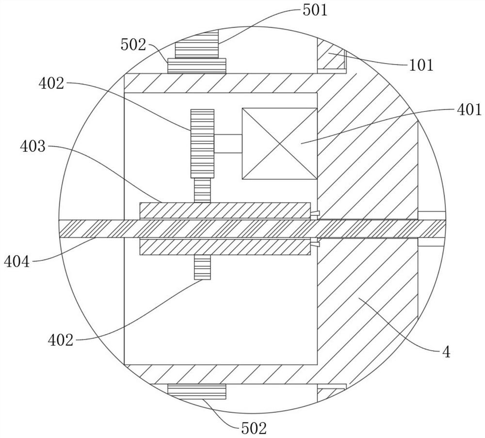
[0035] refer to image 3 , an automatic robot welding auxiliary tool, which is basically the same as that of Embodiment 1, furthermore: the driving mechanism includes a first motor 401, a sleeve 403, and a threaded rod 404, the first motor 401 is fixedly connected in the cylinder 4, and the sleeve One end of the cylinder 403 is rotatably connected to the cylinder 4, the sleeve 403 and the output end of the first motor 401 are fixedly connected with the first gear 402, the two sets of first gears 402 are meshed, and the threaded rod 404 is screwed into the sleeve 403 ;

[0036] The first motor 401 is electrically connected to an external control device;

[0037]By starting the first motor 401 and driving the first gear 402 to rotate, the sleeve 403 is rotated on the mounting bracket 101. The sleeve 403 is provided with threads corresponding to the threaded rod 404. When the sleeve 403 rotates, the threaded rod 404 will be in the The sleeve 403 moves inside, and the threaded r...

Embodiment 3

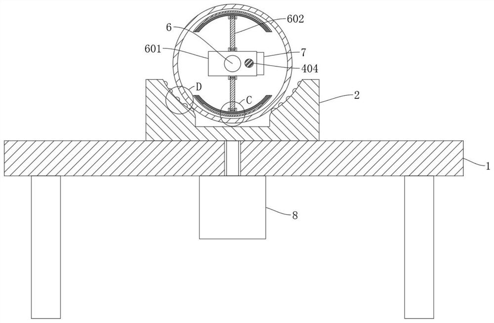
[0039] refer to figure 2 and 6 , an automatic robot welding auxiliary tooling, which is basically the same as that of Embodiment 1, furthermore: a support frame 2 is connected to the workbench 1, the support frame 2 is in a concave arc shape, and the surface of the support frame 2 is in a concave arc shape. There are balls 201, and the support frame 2 is located below the slide bar 6;

[0040] Place the tubular part on the support frame 2, then push the tubular part close to the slide bar 6, and through the friction between the tubular part and the ball 201, it is more labor-saving and easy to push the tubular part;

[0041] At the same time, the center line of the support frame 2 is coaxial with the slide bar 6 , so that the arc-shaped plate 603 can keep the tubular part coaxial with the slide bar 6 when fixing the tubular part.


PUM


Abstract

The invention discloses an automatic robot welding auxiliary tool, and belongs to the technical field of welding auxiliary tools. The automatic robot welding auxiliary tool comprises a workbench, and further comprises a mounting frame, a cylinder, a sliding rod, a first sliding block and a second sliding block, wherein the mounting frame is fixedly connected to the workbench, the cylinder is connected to the mounting frame, one end of the sliding rod is fixedly connected to the cylinder, the first sliding block slides on the sliding rod, and the second sliding block is fixedly connected to the tail end of the sliding rod. According to the automatic robot welding auxiliary tool, the first sliding block drives a connecting rod to change the angle between the connecting rod and the sliding rod, then the distance between an arc-shaped plate and the sliding rod is changed, so that the automatic robot welding auxiliary tool is suitable for tubular parts with different inner circle diameters, the tubular parts are rapidly fixed, and time and labor are saved; meanwhile, a plurality of tools do not need to be manufactured, so that the cost expenditure is saved; and meanwhile, a double-shaft motor is used for driving the cylinder to rotate, then the tubular parts are driven to rotate, and welding is more convenient.

Description

technical field [0001] The invention relates to the technical field of welding auxiliary tooling, in particular to an automatic robot welding auxiliary tooling. Background technique [0002] The welding fixture is a set of flexible fixtures for welding, fixing, pressing and positioning; the three-dimensional flexible welding fixture is widely used in steel structures, various vehicle body manufacturing, rail transit welding, bicycle and motorcycle manufacturing, construction machinery, frames and boxes, Welding and testing systems for pressure vessels, robot welding, sheet metal processing, metal furniture, equipment assembly, industrial piping, etc. [0003] When welding a large number of tubular hollow parts, in order to speed up the welding efficiency, special welding auxiliary tooling will be made according to the tubular parts for positioning the tubular parts. On the one hand, it can speed up the fixing of the tubular parts. On the other hand, the parts can be It can ...

Claims


Application Information

Patent Timeline
IPC IPC(8): B23K37/02B23K37/00B01D46/10
CPCB23K37/0252B23K37/00B01D46/10B01D2258/0283
Inventor 张贺峰罗强张大明
Owner NANJING YUQUN COMM TECH CO LTD
Why Eureka
Try Eureka