On-line detection device for non-contact measuring hole and use method thereof

A detection device and non-contact technology, applied in the field of inspection and detection, can solve the problems of photo quality reduction due to lighting conditions, weak skin rigidity and repeated clamping, unfavorable rapid detection of a large number of holes, etc.

Active Publication Date: 2021-09-10
CHENGDU AIRCRAFT INDUSTRY GROUP
View PDF13 Cites 5 Cited by
  • Summary
  • Abstract
  • Description
  • Claims
  • Application Information

AI Technical Summary

Problems solved by technology

[0004] (1) The contact probe of the three-coordinate measuring machine first needs to be lowered into the connection hole for measurement according to the theoretical hole position of the connection hole. Due to the position error introduced by the artificial hole, the probe is very likely to collide with the skin surface during the descent process. serious accident;
[0005] (2) After the measurement of the part, it is transferred to the CNC machine tool for processing. Due to the weak rigidity of the skin itself and repeated clamping errors, the position of the connecting hole will shift again, resulting in the coaxiality error of the spot facing and the connecting hole
[0006] (3) The three-coordinate measuring machine is a precision equipment, its feed speed is low, and the number of measuring points for a single hole is not less than 8
[0008] (1) The diameter of the hole is only a few millimeters, and the harsh lighting conditions at the production site seriously reduce the quality of the photo;
[0009] (2) Using the camera alone to take pictures can only get the detection results in the plane, but ignores the spatial information of the hole position
For example, the photo contains the information of the hole in the XY plane, but at the same time loses the Z coordinate information of the surface of the hole;
[0010] (3) At present, the non-contact detection equipment is large in size, and it is difficult to integrate with the spindle of the machine tool, which is not conducive to the rapid detection of a large number of hole systems

Method used


Image

  • On-line detection device for non-contact measuring hole and use method thereof
  • On-line detection device for non-contact measuring hole and use method thereof
  • On-line detection device for non-contact measuring hole and use method thereof

Examples


Embodiment 1

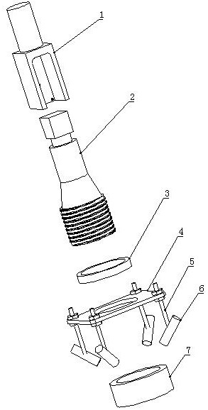
[0073] refer to figure 1 , an online detection device for non-contact measuring holes, including a fixture 1, a camera 2, a snap ring 3, a bracket 4, a coupling rod 5, a laser generator 6, and an illumination compensator 7.

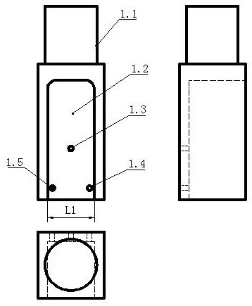
[0074] refer to figure 2 and Figure 4 , the clamp handle 1.1 is a cylindrical structure, the width of the clamp groove 1.2 The width of the upper end of the camera 2.1 The camera upper end 2.1 fits into the fixture groove 1.2 and forms an interference fit. The sides of the fixture groove 1.2 are shaped with apertures of The first light hole 1.3, the second light hole 1.4, and the third light hole 1.5, and the side of the upper end 2.1 of the camera is provided with the first threaded hole 2.2, the second threaded hole 2.3, and the third threaded hole whose thread specifications are all M3 2.4. Camera 2 is equipped with a telecentric lens. refer to Figure 7 , the first screw 8, the second screw 9, and the third screw 10 of which the three thr...

Embodiment 2

[0078] Based on the online detection device for non-contact measuring holes described in Embodiment 1, this embodiment provides an online detection method for non-contact measuring holes, refer to Figure 9 , in order to realize the measurement of the hole, the following steps are included:

[0079] Step 1: Install the jig handle 1.1 of the online detection device on the tool handle 11, and connect the tool handle 11 to the spindle of the machine tool to ensure that the camera 2, the jig handle 1.1, and the spindle of the machine tool are coaxial.

[0080] Step 2: Place the sample 12 with standard holes on the workbench, move the spindle of the machine tool to the top of the hole in the sample 12, that is, the axis of the spindle coincides with the axis of the hole, and move from the light compensator 7 to the upper surface of the sample 12 The strong light is emitted to obtain the compensation light source required by the camera 2 to take pictures, and the laser is emitted fr...

Embodiment 3

[0112] In order to realize the measurement of the hole, the present embodiment provides a kind of online detection method for the non-contact measurement hole. On the basis of Example 2, the method is described with more specific numerical values. The steps are as follows:

[0113] Step 1: Refer to Figure 6 , the fixture handle 1.1 of the online detection device is installed on the tool handle 11, and the tool handle 11 is connected with the machine tool spindle to ensure that the camera 2, the fixture handle 1.1, and the machine tool spindle are coaxial.

[0114] Step 2: Refer to Figure 6 , place the sample 12 with an aperture of φ6 on the workbench, make the center of the hole at X=0, Y=0, and the upper surface of the hole at Z=0. The spindle of the machine tool moves to directly above the hole in the sample 12, that is, the spindle coordinates X=0 and Y=0, emits strong light from the light compensator 7 to the upper surface of the sample 12 so as to obtain the compensati...


PUM


Abstract

The invention discloses an on-line detection device for a non-contact measuring hole and a use method thereof, and belongs to the technical field of on-line detection. The device is structurally characterized by comprising a clamp, a camera, a clamping ring, a support, a connecting rod, a laser generator and an illumination compensator; and the on-line detection device is installed on a machine tool spindle, calibration is conducted at different heights through standard hole samples, a relational expression of a measurement error compensation value and the height of a standard hole is obtained, and geometric parameters of a to-be-detected hole of a part are solved by combining the image recognition technology and an error compensation formula. According to the on-line detection device for the non-contact measuring hole and the use method thereof, non-contact on-line detection of a large number of hole systems can be realized, all geometric information of holes is obtained, probe collision risks and repeated clamping errors caused by contact measurement are eliminated, and the detection efficiency is improved.

Description

technical field [0001] The invention relates to the technical field of inspection and detection, in particular to an on-line detection device for a non-contact measuring hole and a use method thereof. Background technique [0002] With the rapid development of aviation manufacturing technology, the size of modern aircraft is getting bigger and bigger, and the shape is more and more complex. In order to improve the aerodynamic performance of the aircraft under the premise of reducing weight, more and more large composite skins are used as aircraft shape parts. The composite material skin and the metal structure inside the aircraft are first assembled together through positioning holes, and then workers use portable drills to make a large number of connection holes, and then CNC machine tools are used to spot-face the connection holes, and finally workers use pneumatic tools to spot-face the holes Rivets are driven inside to realize the reliable connection between the skin an...

Claims


Application Information

Patent Timeline
Patent Type & Authority Applications(China)
IPC IPC(8): B23Q17/00
CPCB23Q17/00
Inventor 牟文平李博黄明聪张桂李卫东沈昕王鹏程姜振喜
Owner CHENGDU AIRCRAFT INDUSTRY GROUP
Why Eureka
Try Eureka