Renal cancer detection system based on nuclear magnetic resonance, and working method thereof
A nuclear magnetic resonance and detection system technology, applied in the field of detection, can solve the problems of kidney cancer diagnosis error, difficulty in tumor area morphology analysis, unfavorable treatment of kidney cancer, etc.
- Summary
- Abstract
- Description
- Claims
- Application Information
AI Technical Summary
Problems solved by technology
Method used
Image

Examples
Embodiment 1
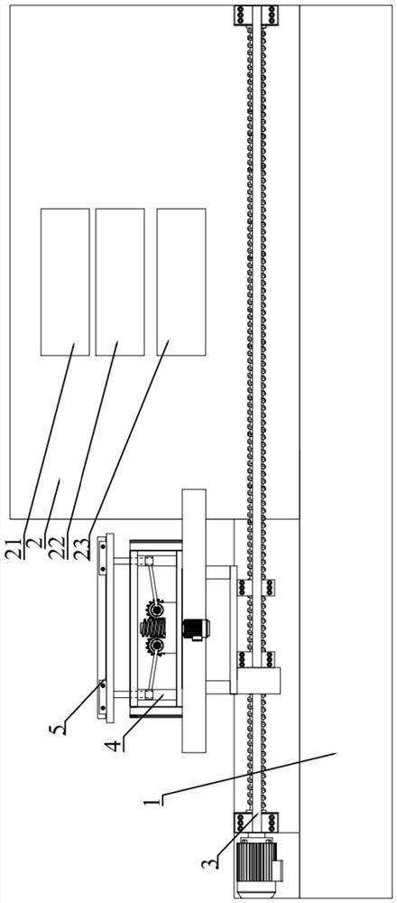
[0041] like figure 1 The shown kidney cancer detection system based on nuclear magnetic resonance includes a base 1, a nuclear magnetic resonance instrument 2, a horizontal feeding unit 3, a lifting adjustment unit 4, a group of sample test tubes 5 and a test tube clamping unit 6, and the nuclear magnetic resonance instrument 2 and the horizontal feeding unit 3 are all arranged on the base 1, one end of the horizontal feeding unit 3 is placed on the nuclear magnetic resonance instrument 2, and the other end of the horizontal feeding unit 3 extends out of the nuclear magnetic resonance instrument 2, and the lifting adjustment The unit 4 is arranged on the horizontal feeding unit 3, and the horizontal feeding unit 3 can drive the lifting adjustment unit 4 to enter or extend out of the nuclear magnetic resonance instrument 2, and the test tube clamping unit 6 is fixedly arranged on the upper end surface of the lifting adjustment unit 4 , the group of sample test tubes 5 is arrang...
Embodiment 2
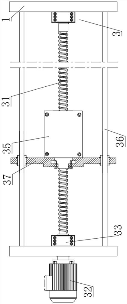
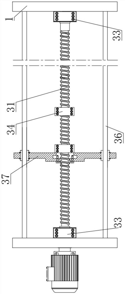
[0045] like figure 2 , 3 The shown horizontal feeding unit 3 comprises a horizontal drive screw 31, a horizontal drive motor 32, a screw support base 33, a group of screw nuts 34 and a horizontal support plate one 35, the horizontal drive motor 32 and the screw support base 33 are all arranged on the base 1, the horizontal drive screw 31 is arranged on the screw support base 33, and the horizontal drive motor 32 is connected with the horizontal drive screw 31, and the set of screw nuts 34 are sleeved on the horizontal drive On the screw rod 31 , the horizontal support plate 1 35 is fixedly connected with a set of screw nuts 34 , and the lifting adjustment unit 4 is fixedly arranged on the upper end surface of the horizontal support plate 1 35 . The base 1 is provided with two guide columns 36, and the two guide columns 36 are symmetrically located on both sides of the horizontal drive screw 31 along the axis, and the guide columns 36 and the horizontal drive screw 31 are arr...
Embodiment 3
[0047] like Figure 4-8 The illustrated lifting adjustment unit 4 includes four guide lifting columns 41, a positioning column driving assembly 42, four positioning guide sleeves 43, four positioning column push rods 44, a fixed mounting plate 45, a horizontal support plate 2 46 and Support frame 40, described support frame 40 is arranged on the horizontal support plate one 35, and described fixed installation plate one 45 and positioning column driving assembly 42 are all arranged on the support frame 40, and described four positioning guide sleeves 43 are arranged on the fixed Between the mounting plate one 45 and the positioning column drive assembly 42, the four guiding lifting columns 41, the four positioning guide sleeves 43 and the four positioning column push rods 44 are provided in one-to-one correspondence, and the four positioning column push rods 44 One end of the positioning column driving assembly 42 is connected, and the other end of the positioning column push ...
PUM
 Abstract
Description
Claims
Application Information
 - R&D
- Intellectual Property
- Life Sciences
- Materials
- Tech Scout
- Unparalleled Data Quality
- Higher Quality Content
- 60% Fewer Hallucinations
Browse by: Latest US Patents, China's latest patents, Technical Efficacy Thesaurus, Application Domain, Technology Topic, Popular Technical Reports.
© 2025 PatSnap. All rights reserved.Legal|Privacy policy|Modern Slavery Act Transparency Statement|Sitemap|About US| Contact US: help@patsnap.com