An out-of-plane thermoelectric device with stretchable porous structure

A thermoelectric device and porous structure technology, which is applied in the manufacture/processing of thermoelectric devices, thermoelectric device components, and thermoelectric devices, can solve the problems of large contact thermal resistance, non-stretchable devices, and establishment of temperature differences, etc., to achieve Effect of Reducing Interface Thermal Resistance

Active Publication Date: 2022-07-26
BEIHANG UNIV
View PDF19 Cites 0 Cited by
  • Summary
  • Abstract
  • Description
  • Claims
  • Application Information

AI Technical Summary

Problems solved by technology

First, flexible devices based on high-performance inorganic thermoelectric materials, due to the high thermal conductivity of thermoelectric materials, it is difficult to establish a temperature difference between the two sides of the thermoelectric materials in human body applications; second, the existing flexible thermoelectric devices, the use of low The polymer substrate with thermal conductivity causes large heat loss, which is not conducive to the utilization of heat energy
Third, the existing flexible thermoelectric devices are limited by the non-stretchability of the electrodes, so the device itself is not stretchable; fourth, the contact thermal resistance between the substrate of the flexible thermoelectric device and the heat source is relatively large, so that the two sides of the thermoelectric arm The actual temperature difference on the side is small, which affects the thermoelectric conversion efficiency

Method used


Image

  • An out-of-plane thermoelectric device with stretchable porous structure
  • An out-of-plane thermoelectric device with stretchable porous structure
  • An out-of-plane thermoelectric device with stretchable porous structure

Examples


Embodiment Construction

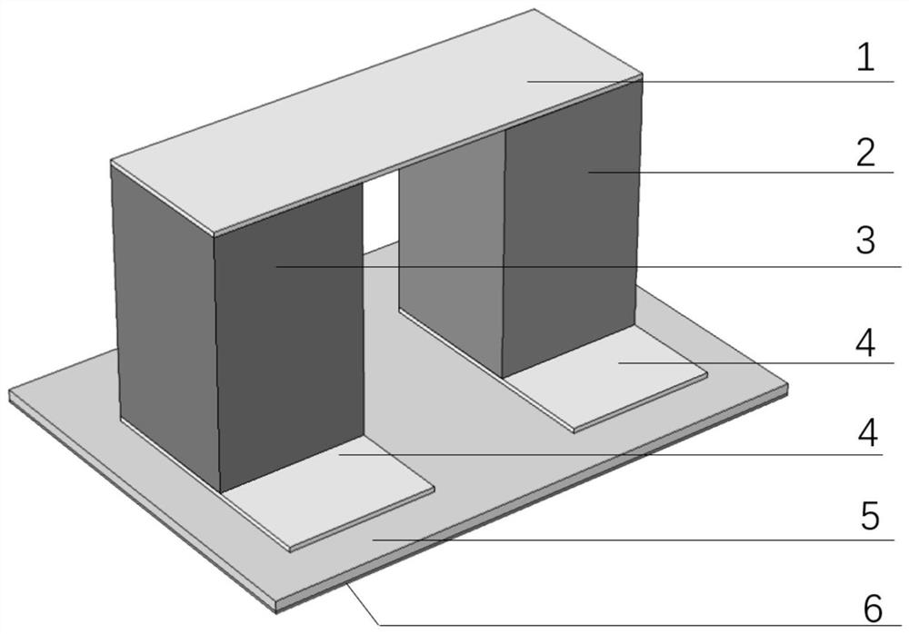
[0051] figure 1 The device structure diagram of a pair of thermoelectric arms, the top electrode (1) and the bottom electrode (4) composed of conductive cloth, p-type thermoelectric arms (2) and n-type thermoelectric arms composed of flexible porous materials with low thermal conductivity and thermoelectric materials The thermoelectric arm (3) is a flexible and highly thermally conductive substrate composed of a flexible stretchable film (5) with high thermal conductivity and a metal interface layer (6) with high thermal conductivity.

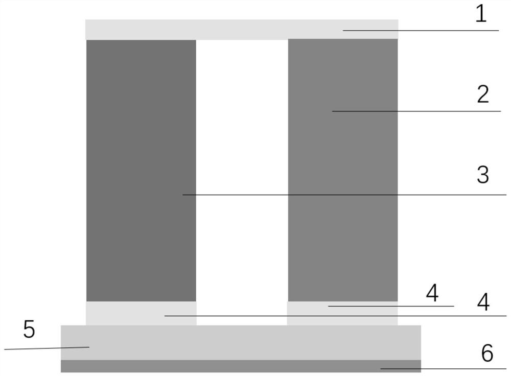
[0052] figure 2 It is a device front view of a pair of thermoelectric arms, the p-type thermoelectric arm (2) and the n-type thermoelectric arm (3) are connected to the top electrode (1) and the bottom electrode (4) through silver paste. The bottom electrode (4) is adhered to the upper surface of the flexible film (5) through the self-adhesive surface of the conductive cloth. The metal interface layer (6) is fixed on the lower surface of the...


PUM

PropertyMeasurementUnit
thicknessaaaaaaaaaa
thicknessaaaaaaaaaa
thicknessaaaaaaaaaa

Abstract

The invention relates to an out-of-plane thermoelectric device with a stretchable porous structure, belonging to the technical field of flexible thermoelectric energy conversion. The thermoelectric device consists of the following structures: a top electrode (1) and a bottom electrode (4) composed of conductive cloth, p-type thermoelectric arms (2) and n-type thermoelectric arms composed of flexible porous materials with low thermal conductivity and thermoelectric materials (3), a flexible and high thermal conductivity substrate composed of a flexible stretchable high thermal conductivity film (5) and a high thermal conductivity metal interface layer (6). The technical problems to be solved by the present invention are: constructing an elastic material integrating thermoelectric energy conversion function and three-dimensional porous structure to obtain a stretchable thermoelectric material; designing the electrode structure of the thermoelectric device, reducing the interface thermal resistance between the thermoelectric device and the heat source, and improving the The actual temperature difference between the hot and cold sides of the thermoelectric device improves the output voltage performance of the device, and realizes the stretchable application of the wearable power supply application where the device uses human body temperature to generate electricity.

Description

technical field [0001] The invention relates to an out-of-plane thermoelectric device with a stretchable porous structure, belonging to the technical field of flexible thermoelectric energy conversion. Background technique [0002] Devices used in wearable sensing systems should have the characteristics of sustainable operation, independence, maintenance-free, and mechanical flexibility. There is no doubt that in the process of sensing and signal transmission, power supply is an indispensable part. However, the current power supply unit has become the biggest limitation of the wearable sensor network to achieve the above functions, because the most widely used power supply system is the block battery, which brings a series of problems such as wearable flexibility, frequent charging problems and battery replacement. And other issues. As more and more sensors are used in remote control scenarios, self-powered sensing devices that do not require an external power supply unit ...

Claims


Application Information

Patent Timeline
Patent Type & Authority Patents(China)
IPC IPC(8): H01L35/02H01L35/32H01L35/34
CPCH10N10/80H10N19/101H10N10/01
Inventor 王瑶王亚龙邓元
Owner BEIHANG UNIV
Why Eureka
Try Eureka