Separated lens antenna and communication equipment

A lens antenna, in vitro technology, applied to antennas, antenna arrays, antenna arrays that are individually powered, etc., can solve the problems of narrow beam width and lack of one-dimensional continuous beam scanning capability.

Pending Publication Date: 2021-09-10
SHENZHEN SUNWAY COMM
View PDF0 Cites 0 Cited by
  • Summary
  • Abstract
  • Description
  • Claims
  • Application Information

AI Technical Summary

Problems solved by technology

However, this lens antenna has a narrow beam width and does not have the capability of one-di

Method used


Image

  • Separated lens antenna and communication equipment
  • Separated lens antenna and communication equipment
  • Separated lens antenna and communication equipment

Examples


Embodiment 1

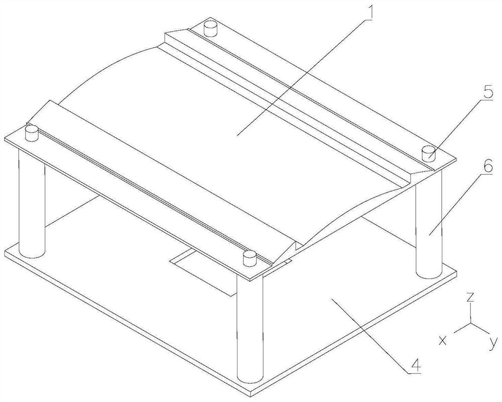
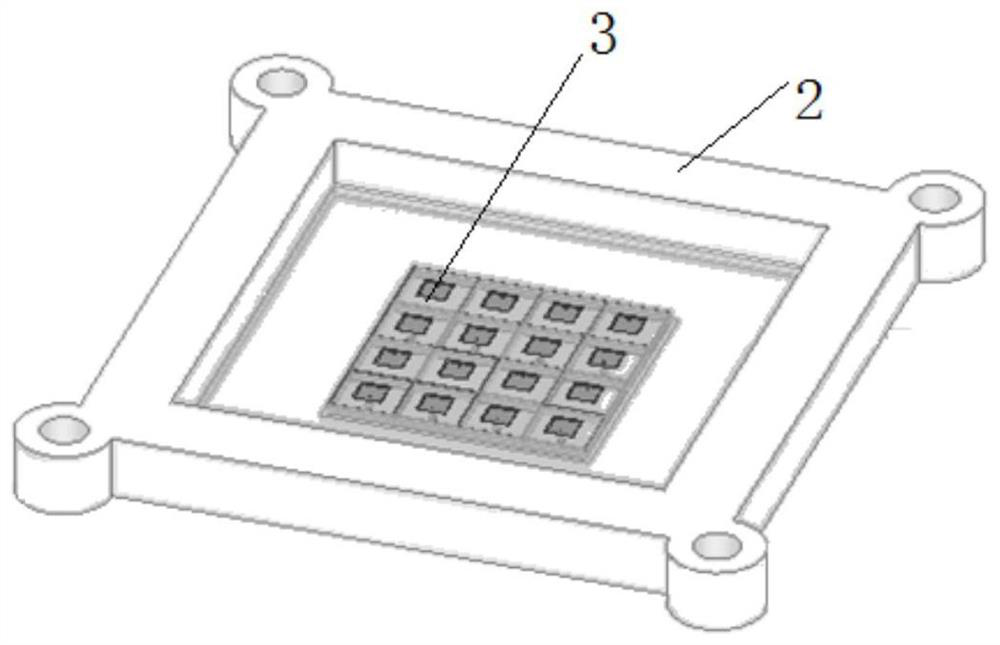
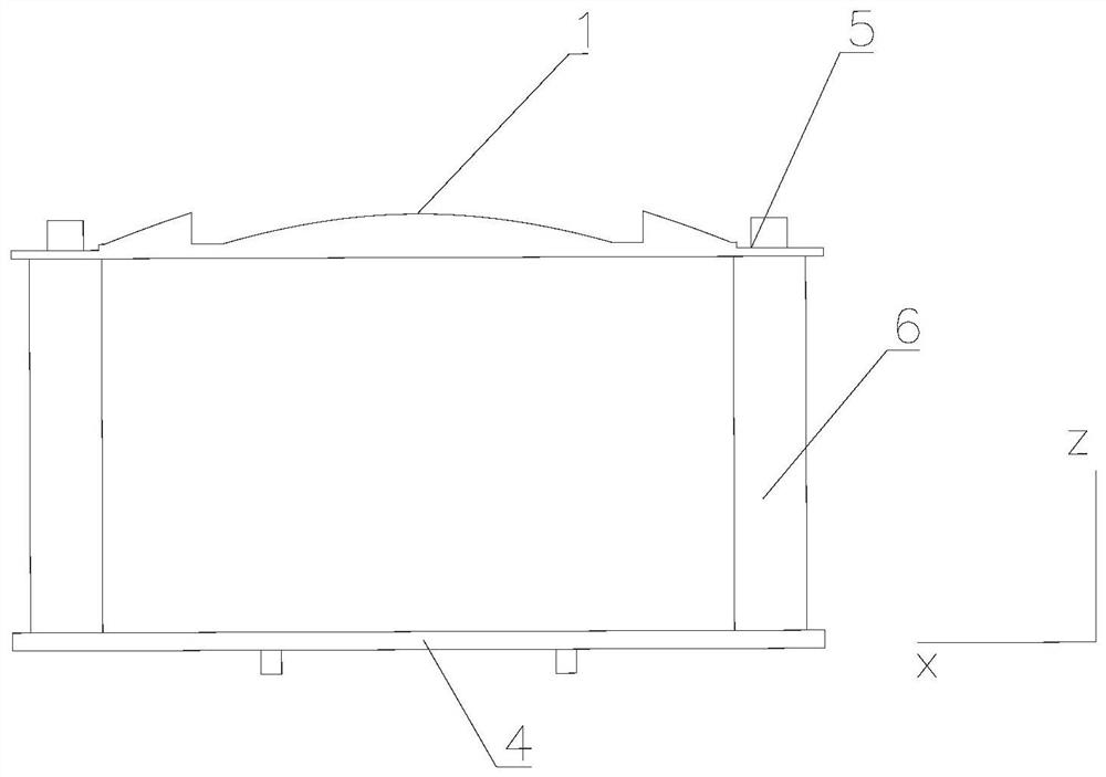
[0055] Please refer to figure 1 and figure 2 , an isolated lens antenna, comprising a dielectric lens 1, a base 2, a microstrip radiation unit 3 and a lens holder 4; the dielectric lens 1 is arranged on one side of the lens holder 4; one side of the dielectric lens 1 It is a plane, and the other side is a convex surface whose height varies along a single dimension; the other side of the lens holder 4 is connected to the base 2; the microstrip radiation unit 3 is arranged on one side of the base 2, and Located in the base 2; the distance from the dielectric lens 1 to the microstrip radiation unit 3 is equal to the focal length of the dielectric lens 1; the base 2 is provided with a groove near the side of the lens holder 4; the The microstrip radiation unit 3 is arranged in the groove;

[0056] Please refer to Figure 1 to Figure 4 , the dielectric lens 1 in this embodiment is composed of an integrated medium, one side of the integrated medium is a plane, and the other side...

Embodiment 2

[0060] The difference between this embodiment and Embodiment 1 is that this embodiment limits the composition of the lens;

[0061] Please refer to Figure 5 , the dielectric lens 1 includes a plurality of dielectric pillars 7 with different heights; one side of the plurality of dielectric pillars 7 is spliced ​​to form the plane; the other side of the plurality of dielectric pillars 7 is in a preset first dimension There is a height change in the direction, and the convex surface with uneven height is formed by the height change in a single dimension direction;

[0062] Specifically, please refer to Image 6 , the medium column 7 is a cylinder; the sides of the adjacent cylinder medium columns 7 are tangent; one side of the plurality of cylinders is on the same plane, and the other side of the plurality of cylinders forms The height change in the single-dimensional direction; the cylindrical dielectric column 7 has different height changes along the x-axis direction, wherei...

Embodiment 3

[0065] The difference between this embodiment and Embodiment 1 or 2 is that the direction of the lens convex surface is limited;

[0066] In an alternative implementation, please refer to figure 1 and Figure 5 , the plane of the dielectric lens 1 is set towards the base 2; as in Embodiment 1 and Implementation 2, the convex surface of the lens antenna is set on the side away from the base 2;

[0067] In another alternative implementation, please refer to Figure 7 and Figure 8 , the convex surface of the dielectric lens 1 is set towards the base 2; specifically, take the cylindrical dielectric column 7 in Embodiment 2 as an example; the cylindrical dielectric column 7 has different height changes along the x-axis direction At the same time, the direction of its height change is toward the negative semi-axis direction of the z-axis, that is, extending toward the base 2; and the height direction of the cylindrical dielectric column 7 is changed along the negative semi-axis ...


PUM


Abstract

The invention discloses a separated lens antenna and communication equipment. One side of a dielectric lens is arranged to be a plane, the other side of the dielectric lens is arranged to be a convex face with the height changing in the single-dimension direction, and the dielectric lens is arranged at the position where the distance between the dielectric lens and a micro-strip radiation unit equals the focal length of the dielectric lens through a lens support, so that electromagnetic waves can be fully diffused when propagating between the micro-strip radiation unit and the lens, and when propagating to the dielectric lens, the electromagnetic waves can be radiated to the outer side of the dielectric lens only after passing through the convex surface of which the height changes along the single-dimensional direction; therefore, the phase change of the electromagnetic wave is changed only in a single-dimensional direction, and the phase change of the electromagnetic wave in other dimensional directions is not changed, so that the radiation gain of the antenna is enhanced, and the beam direction of the electromagnetic wave radiated by the microstrip radiation unit is ensured to be consistent with the beam direction of the electromagnetic wave emitted after passing through the dielectric lens. Therefore, continuous scanning of the antenna in the one-dimensional direction is realized.

Description

technical field [0001] The invention relates to the field of antennas, in particular to an isolated lens antenna and communication equipment. Background technique [0002] With the development of 5G technology, the applicable field of lens antenna technology is also expanding. Such as increasing the gain of the antenna and the area for receiving electromagnetic waves by increasing the dielectric lens. However, the phase distribution mode of the conventional lens antenna structure is a concentric circle structure. Although this structure can maximize the use of the lens surface, the area of ​​the antenna aperture is increased to increase the antenna gain. However, this lens antenna has a narrow beam width and does not have the capability of one-dimensional continuous beam scanning, so it cannot be widely used in the millimeter wave field. Contents of the invention [0003] The technical problem to be solved by the present invention is to provide an off-body lens antenna ...

Claims


Application Information

Patent Timeline
IPC IPC(8): H01Q15/08H01Q19/06H01Q1/12H01Q1/36H01Q21/06
CPCH01Q15/08H01Q19/06H01Q1/12H01Q1/36H01Q21/061
Inventor 唐小兰赵伟谢昱乾杨扬
Owner SHENZHEN SUNWAY COMM
Why Eureka
Try Eureka